
ANTIS
ENERGY / 01 ANTIS Energy
Humidity Control for Energy Storage and Electrical Environments
ANTIS focuses on equipment and project support for enclosed energy and electrical applications where condensation, corrosion, installation space, and operating reliability need careful review.
Tell us about the enclosure — how big it is, how much heat it holds, and where it will be installed. From there we can narrow the equipment options quickly.
Equipment selection starts with the enclosure. Ambient conditions, internal heat, available space, drainage, power, and controls help determine the suitable equipment and configuration.
CONDENSATION FUNDAMENTALS
Condensation starts when a surface falls below the dew point of the air around it
Relative humidity is useful, but it is not the whole decision. The same air can show a higher RH after cooling even when no water has entered the enclosure. Condensation begins when a busbar, cabinet wall, cable terminal, cooling pipe, door frame, or other surface becomes colder than the dew point of the air touching it.
Dew point
Air moisture
Dew point describes the moisture content of the air more directly than RH alone. Lowering it creates more margin before a cold surface becomes wet.
Measure it near representative return air and compare it with the temperature of the most vulnerable surfaces.Surface temperature
Surface condition
Cabinet skins, cable entries, cooling lines, metal frames, and components do not all follow the same temperature. The coldest practical surface often sets the risk.
Use measured surface temperature where possible instead of assuming it equals the enclosure air temperature.Control margin
Operating reserve
A project needs enough separation between surface temperature and dew point to tolerate sensor error, weather change, door opening, and equipment cycling.
The required margin belongs in the project control strategy; it should not be replaced by one universal RH setpoint.WHY CONDENSATION APPEARS
Risk often rises during transitions rather than at the nominal operating point
A cabinet can appear dry during steady operation and still condense after charging, discharge, standby, night cooling, HVAC cycling, maintenance, or a sudden weather change. Internal losses warm some parts of the enclosure while doors, skins, cable glands, and inactive components may remain cooler. When the heat source stops or cooling continues, the surface and air temperatures can move at different rates.
Charge and discharge cycles
Component losses, cooling response, and changing airflow create local temperature differences. Review the warm-up and cool-down period as well as the steady state.
HVAC cycling
Cooling may remove water at the coil, but a stopped compressor, continuing fan, short cycle, or cold supply surface can leave a temporary condensation risk elsewhere.
Day, night, and season
Solar gain, rain, night cooling, cold fronts, monsoon humidity, and winter warm-air ingress can move the enclosure across the dew point in different ways.
Maintenance and door opening
Opening a dry enclosure in humid weather can introduce a short, concentrated moisture load. Recovery time and operating sequence should be planned.
DIAGNOSTIC SIGNALS
Locate when and where water appears before deciding how to remove it
A single RH value does not identify the moisture source. Record the time, location, operating mode, door status, ventilation state, equipment temperature, alarms, and visible condition. Compare these observations with surface temperature and dew point. The result should distinguish a local cold-surface problem from a persistent enclosure-wide moisture load.
Water location
Record whether water forms on the cabinet skin, cable terminals, busbars, insulation, cooling pipes, floor, door frame, or equipment directly below an air outlet.
Time and event
Note whether the symptom follows rain, night cooling, standby, charge or discharge, HVAC shutdown, door opening, washing, or a maintenance period.
Sensor disagreement
Compare more than one point. A warm controller compartment may show acceptable RH while a lower cable area or outside wall is already close to the dew point.
Drain and trench condition
Check condensate lines, traps, drain slopes, floor penetrations, cable trenches, standing water, and vapour paths from below the enclosure.
Electrical trend
Where the project already records insulation resistance, leakage, corrosion, or alarm history, compare the trend with weather and operating events rather than treating it as a humidity setpoint.
ENCLOSURE LOAD MAP
Five inputs determine how much moisture control the enclosure actually needs
Capacity follows the moisture load and the recovery window, not a simple litres-per-cubic-metre rule. A useful calculation accounts for the air initially inside the enclosure, humid outside air entering over time, moisture from wet trenches or materials, drainage behaviour, and the time available to restore the required condition.
Volume and initial condition
Record internal free volume, starting temperature and humidity, target condition, and the air or material mass that must be dried after installation or service.
Internal heat and cold surfaces
Map batteries, PCS, transformers, electronics, cooling coils, pipes, cabinet skins, and shaded or exposed faces. These locations set temperature differences and condensation risk.
Air exchange and leakage
Include planned ventilation, pressure equalisation, fan operation, service doors, cable glands, construction joints, and repeated maintenance access.
Liquid water and drainage
Identify coil condensate, dehumidifier condensate, rain ingress, trench water, washdown, drain height, hose route, trap, lift, freeze risk, and alarm needs.
Control and recovery window
Define how quickly the enclosure must recover after opening or a high-humidity event and how much equipment cycling or redundancy the project allows.
APPLICATION ENVIRONMENTS
The enclosure type changes the temperature, installation, corrosion, and service constraints
Energy projects do not share one standard cabinet. A 20 ft BESS container, a narrow outdoor cabinet, a wind-turbine nacelle, a cable trench below switchgear, and a data hall expose equipment to different air volumes, heat sources, weather, salt, dust, vibration, access, and maintenance schedules.
01
BESS containers
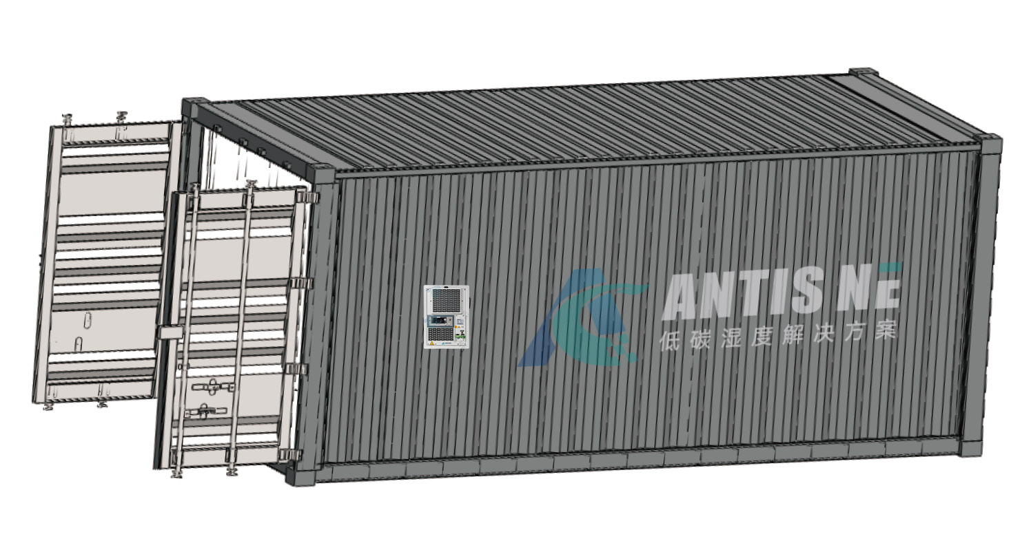
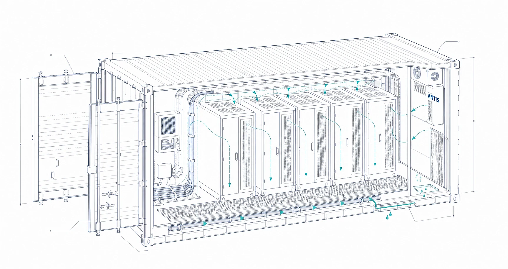
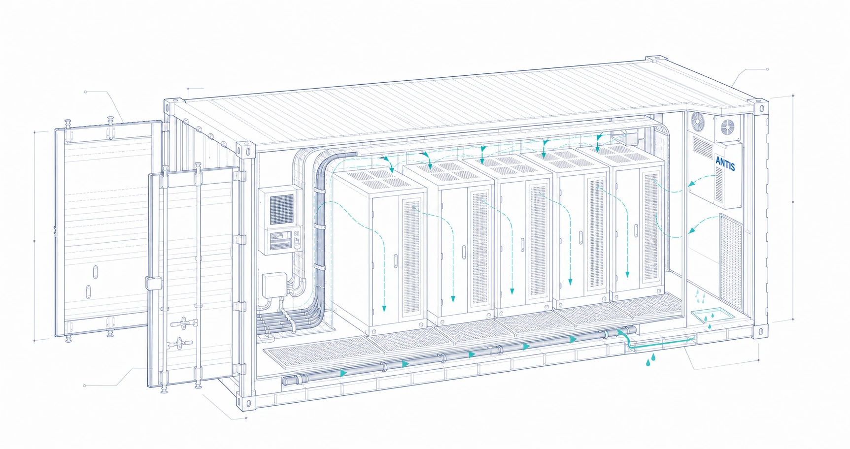
Review internal heat, HVAC sequence, door recovery, air distribution, drainage, fire and gas-control interfaces, and the surfaces most likely to fall below dew point. ADS-10D is a current 10 L/24h compact refrigerant option for suitable 20 ft container duties.
02
C&I cabinets and PCS
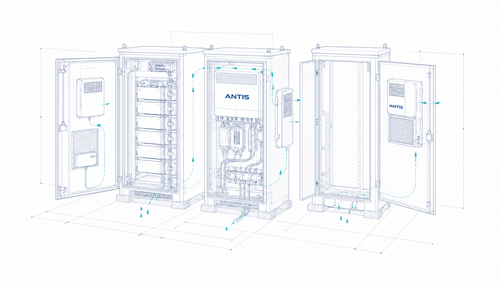
Free depth and power can be tighter than moisture capacity. ADS-100WB-01 and ADS-100WB-06 use a 65 mm or 90 mm class body depth for door or cabinet integration, while ADS-500ML and ADS-1000ML serve smaller loads.
03
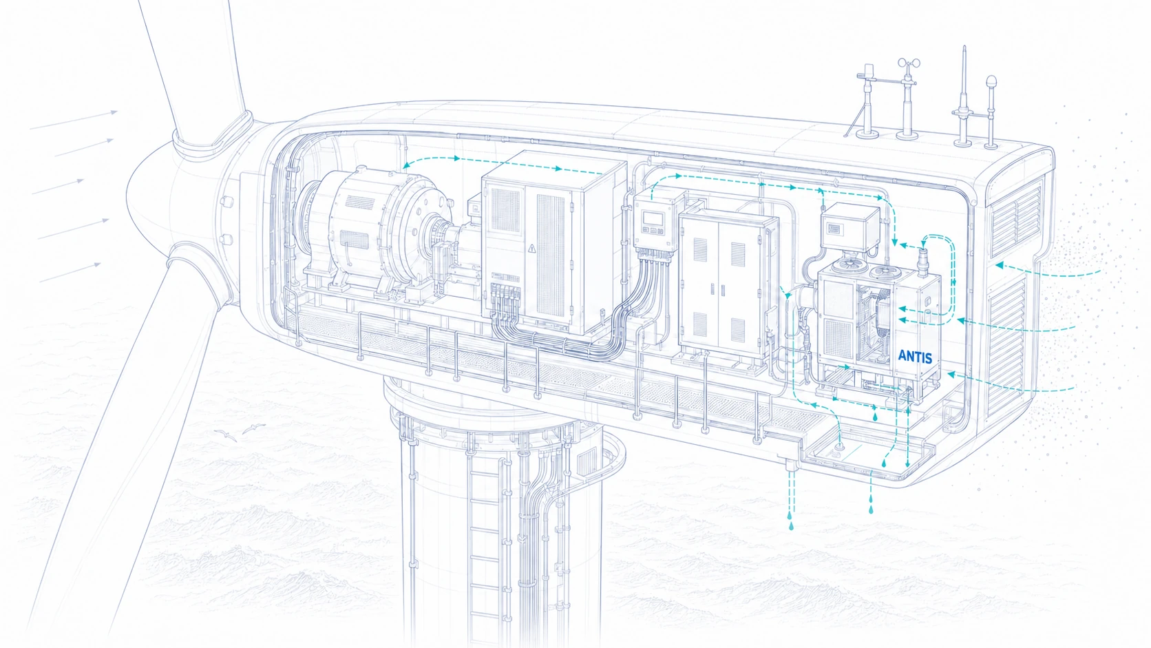
Wind nacelles and towers
Low temperature, salt spray, long service intervals, vibration, regeneration air, discharge routing, and restricted access can favour a project-specific desiccant configuration. Guangdong offshore wind projects use salt-spray-resistant ADS-500M units. A China Energy Investment Group wind-farm project uses custom anti-salt-spray desiccant equipment in one nacelle and two tower positions.
04
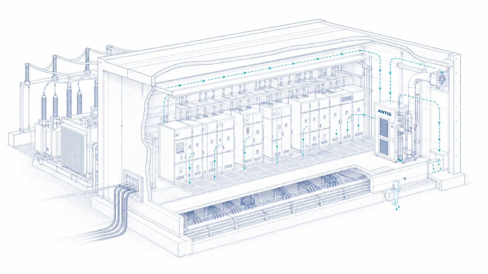
Power grid and substations
Switchgear rooms, box transformers, cable spaces, and substations may combine wet trenches with low winter temperature and large leakage paths. Review cable trenches, ventilation, cold surfaces, access, drainage, and the required recovery time before selecting the control method.
05
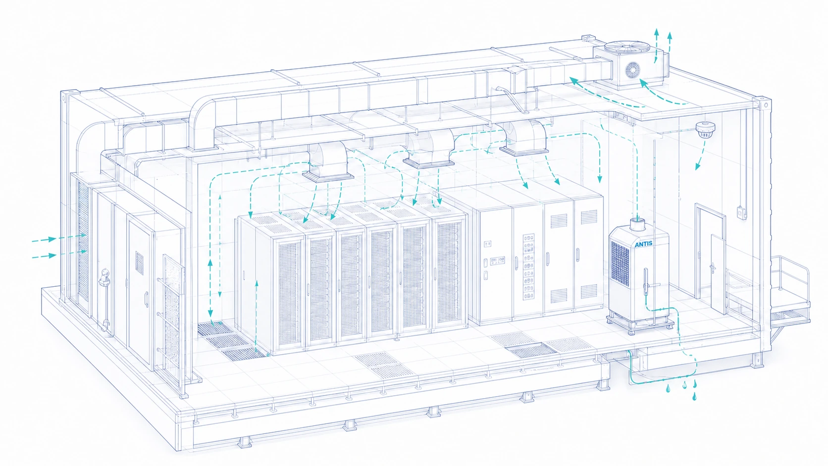
Data centres and technical rooms
Moisture limits, rack inlet conditions, cooling operation, filtration, corrosion, and sensor placement must follow the IT equipment and facility standard. Larger refrigerant units may apply, but they are reviewed separately from compact cabinet products.
CONTROL PATHWAYS
Choose whether the project must block moisture, exchange air, warm surfaces, remove water, or combine them
Sealing reduces uncontrolled moisture entry. Ventilation exchanges air and may be required for heat or gas management. Heating raises surface temperature and can increase the dew-point margin, but it does not remove water from a closed enclosure. Dehumidification physically removes or transfers moisture. Each method answers a different part of the problem.
Seal and dehumidify
Useful when outside air is frequently humid and the enclosure can be kept reasonably tight. Confirm leakage, door events, drainage, heat rejection, and recovery time.
Ventilation-led
Appropriate when outside air is dry enough and air exchange is compatible with thermal, contamination, gas, and weather requirements. It cannot be assumed to dry the enclosure in humid weather.
Surface heating
Useful for selected cold surfaces or low-load cabinets when raising temperature provides enough margin. Check energy use, hot spots, component limits, and what happens after the heater cycles off.
Combined control
Coordinate sealing, ventilation, heating, cooling, circulation, and dehumidification under one operating sequence. Define priorities so systems do not fight each other.
EQUIPMENT SELECTION
Compare ANTIS equipment with the real duty, installation space, power, and operating temperature
The model cards use current catalog data. Capacity values are ratings at the stated test condition, not a promise of the same removal rate at every enclosure condition. Final selection also needs the moisture load, recovery window, location, power, drainage, control interface, access, and quantity.
Compact refrigerant units
For BESS containers and electrical cabinets operating within the model temperature range, with continuous condensate drainage and enough clearance for airflow and service.
Compare rated capacity, AC or DC supply, body depth, drainage path, mounting side, heat effect, and recovery duty.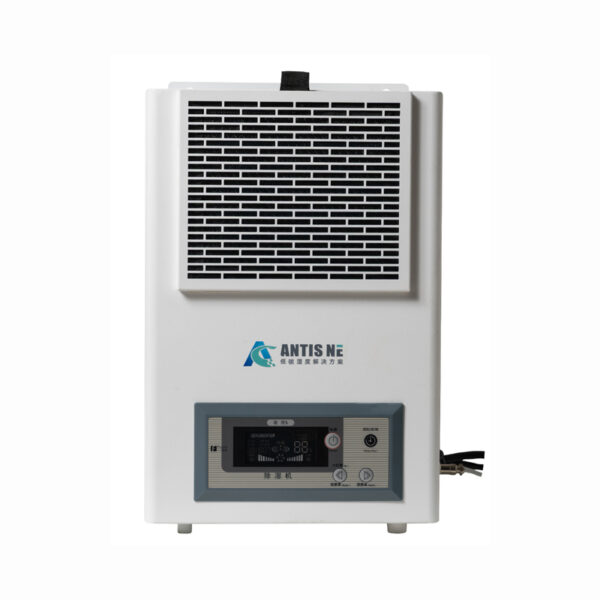
ADS-10D
- Dehumidification Capacity
- 10 L/24h
- Rated Power
- 185 W
- Operating Temperature
- 5–40 °C
- Power Supply
- AC 220V 50Hz
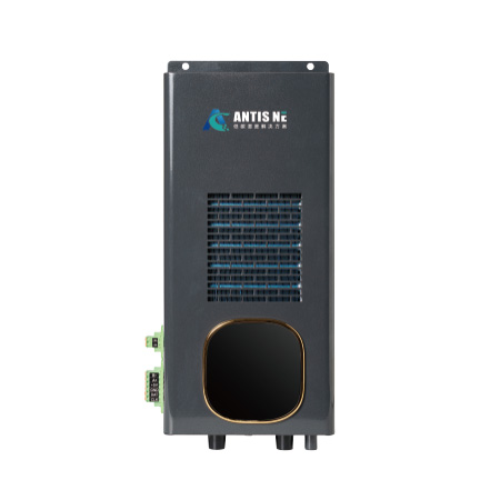
ADS-100WB-01
- Dehumidification Capacity
- 4 L/24h
- Rated Power
- 120 W
- Operating Temperature
- 5–40 °C
- Power Supply
- DC 24V
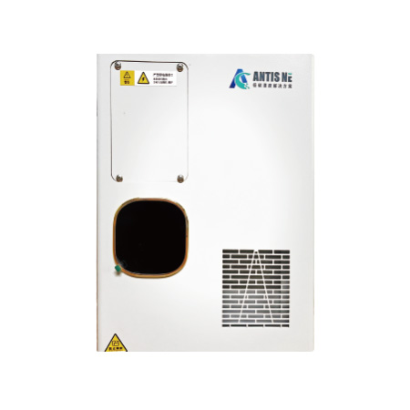
ADS-100WB-06
- Dehumidification Capacity
- 6 L/24h
- Rated Power
- 150 W
- Operating Temperature
- 5–40 AC / 5–45 DC
- Power Supply
- AC 220V / DC 24V
Semiconductor cabinet units
For small electrical enclosures and lower moisture loads where compact construction and a broad operating-temperature range matter more than high daily water removal.
Review cabinet heat balance, drainage, 24 VDC or AC supply, sensor position, alarm logic, and the actual moisture-entry rate.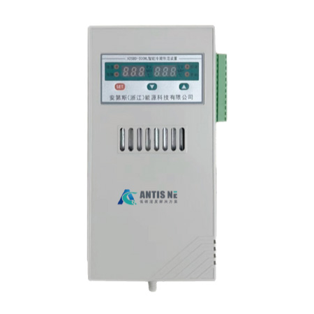
ADS-500ML
- Dehumidification Capacity
- 500 mL/24h
- Rated Power
- 60 W
- Operating Temperature
- -30–+55 °C
- Power Supply
- AC 220–240V / DC 24V
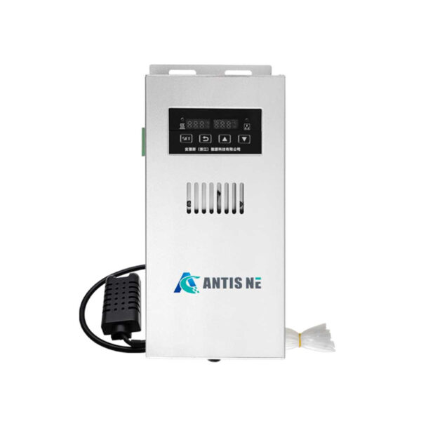
ADS-1000ML
- Dehumidification Capacity
- 1000 mL/24h
- Rated Power
- 150 W ABS / 120 W aluminium
- Operating Temperature
- -30–+55 °C
- Power Supply
- AC 220V / DC 24V
Energy desiccant systems
For wind, grid, substation, low-temperature, low-dew-point, or salt-exposed duties that require a project-specific desiccant configuration.
Confirm process and regeneration airflow, regeneration heat, discharge, pressure, temperature, salt exposure, vibration, maintenance interval, and controls.Higher-capacity refrigerant systems
For data centres, larger technical rooms, industrial spaces, and warehouses where cabinet-scale products do not match the total moisture load or air-distribution requirement.
Confirm rated condition, airflow, power, operating temperature, drainage, room distribution, redundancy, and integration with the existing HVAC system.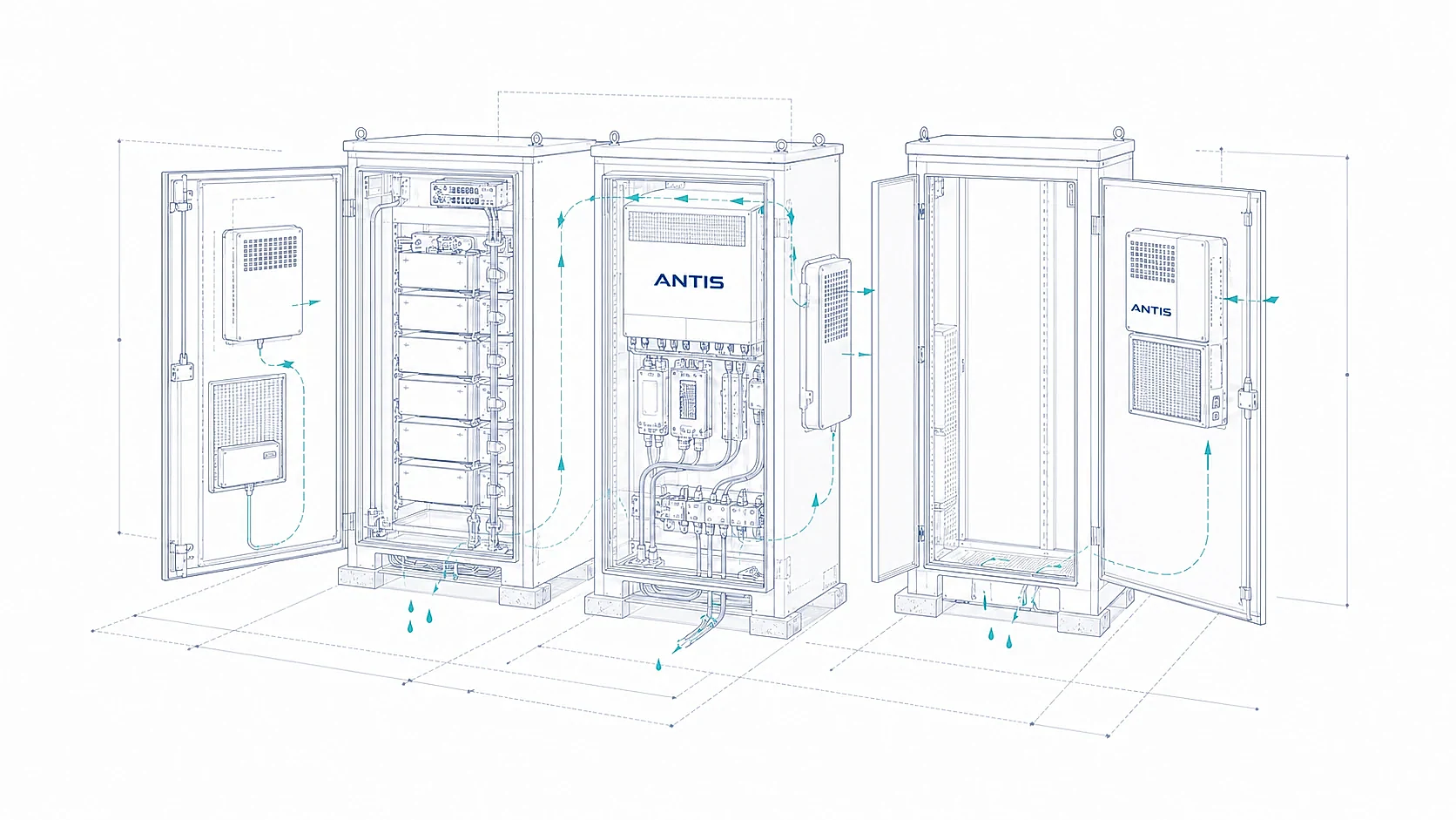
SYSTEM INTEGRATION
Plan drainage, sensors, alarms, communications, and multi-cabinet operation before installation
Moisture removed from the air must leave the enclosure safely. Route condensate to a suitable drain or collection point with the required fall, lift, trap, freeze protection, leak detection, and service access. A hose that terminates inside a sealed cabinet only moves the problem.
Condensate route
Define drain destination, hose material, slope, trap, lift, freeze risk, blockage detection, service access, and what the enclosure should do after a drain alarm.
Sensors and control point
Place sensors where they represent the air and surfaces at risk. Define calibration, polling, deadband, delay, priority, and behaviour during HVAC or door events.
BMS and EMS interface
List required signals, protocol, register map, alarm states, remote commands, data frequency, and cybersecurity or gateway constraints. Confirm each item against the selected configuration.
Repeated deployment
Freeze model, firmware, setpoints, alarm mapping, drain details, inspection records, and acceptance tests so multiple cabinets can be commissioned and maintained consistently.
ENGINEERING SUPPORT
Connect the selected equipment to the wider enclosure and project requirements
Yakeclimate designs and manufactures industrial dehumidification equipment for complex climate applications, with a focus on agriculture and energy projects. We co-develop application-specific dehumidification equipment around the operating conditions, interfaces, and integration requirements of the wider project or system.
01 / Define the operating condition
Confirm enclosure geometry, project location, ambient and internal trends, surface risk, moisture sources, operating events, target, and recovery window.
02 / Compare equipment and placement
Review technology, capacity, temperature range, power, mounting, air path, drainage, heat effect, service access, redundancy, and quantity.
03 / Confirm interfaces and evidence
Agree controls, alarms, communications, drawings, test scope, destination documentation, corrosion requirements, and responsibilities between project parties.
04 / Build and validate the configuration
Manufacture the agreed equipment, complete the required checks and records, and prepare installation and commissioning information for the project team.
TESTING AND VALIDATION
Match project evidence to the exact equipment, environment, and destination
Installed work provides application evidence. At a coastal energy-storage site in Zhuhai, one ADS-10D replaced four semiconductor units and brought the container from saturated to stable dry conditions in three to four hours. Offshore wind projects in Guangdong use salt-spray-resistant ADS-500M units. A China Energy Investment Group wind farm operates custom anti-salt-spray desiccant equipment with one unit in the nacelle and two in the tower.
Validation capability includes an in-house enthalpy-difference laboratory, Yakeclimate's own salt-spray chamber, and CNAS-accredited salt-spray test reports. The available drawing, manual, inspection record, test evidence, and compliance document still has to be checked against the exact model, configuration, destination, and project scope. No expired or unrelated certificate should be presented as coverage for a selected model.
Application record
Use site condition, installed configuration, operating result, and maintenance context to judge whether a previous project is genuinely comparable.
Environmental validation
Review salt, corrosion, temperature, humidity, ingress, vibration, and other environmental requirements against the agreed construction and test scope.
Product evidence
Match ratings, drawings, materials, controls, and documentation to the exact model and revision rather than relying on a family-level claim.
Commissioning evidence
Record sensor calibration, setpoints, alarms, drain operation, recovery test, operating mode, and acceptance criteria for the installed system.
FREQUENTLY ASKED QUESTIONS
Questions to resolve before selecting humidity-control equipment for an energy enclosure
These answers establish the first engineering boundary. They do not replace the BESS, electrical, ventilation, fire, HVAC, or enclosure design. Send the actual conditions and selected equipment requirements so ANTIS can confirm what applies.
01Why can a BESS container condense even when it has air conditioning?
Cooling can remove moisture at the coil, but condensation is decided locally. A cold supply surface, cabinet skin, pipe, cable area, short HVAC cycle, door opening, or post-operation cool-down can fall below the surrounding dew point. Review surface temperature, dew point, air distribution, cycle timing, drainage, and outside-air entry.
02Can ventilation and dehumidification replace each other?
Not automatically. Ventilation exchanges air and may serve heat or gas-control duties. It dries only when the entering air carries less moisture than the air it replaces. Dehumidification removes moisture without relying on favourable outdoor air. Calculate safety ventilation and humidity control as separate functions, then coordinate their operation.
03Does an IP65 enclosure eliminate the need for humidity control?
No. An IP rating classifies protection against contact, solid objects, and harmful water ingress under defined tests. It does not state that the enclosure is vapour-tight, eliminate moisture trapped during assembly, or prevent condensation caused by temperature change. Review seals, pressure paths, cable entries, door events, and internal dew point.
04Where should condensate go in a sealed cabinet or container?
Route condensate outside the protected space or to an approved collection and disposal system. Define hose slope, lift, trap, freeze risk, blockage detection, leak response, and service access. Test the drain under the actual equipment position before accepting the installation.
05Why do coastal and offshore projects need a separate corrosion review?
Humidity and salt deposits can create a more aggressive conductive and corrosive surface condition. Review material, coating, fasteners, heat exchangers, electronics, drainage, filtration, service interval, and the required salt-spray evidence for the exact configuration. ANTIS has project experience with salt-resistant ADS-500M and custom wind-power equipment.
06When is a desiccant unit more suitable than a refrigerant unit?
Desiccant equipment can be considered at lower temperature, toward a lower dew point, or where the refrigerant unit cannot deliver the required duty. It also needs process and regeneration airflow, heat input, discharge, controls, and maintenance. Compare performance at the real condition rather than selecting by technology name.
07How large a dehumidifier does a 20 ft BESS container need?
There is no universal capacity based only on container size. Calculate initial moisture, air leakage, door opening, wet materials or trenches, HVAC removal, surface risk, target dew point, and recovery time. ADS-10D is rated at 10 L/24h at 30 °C and 80% RH for suitable 20 ft applications, but the project duty still requires review.
08Can the dehumidifier connect to an existing BMS or EMS?
It can when the selected configuration supports the required interface. Send the protocol, signal list, register expectations, alarm states, remote commands, gateway constraints, and data interval. ADS-500ML and ADS-1000ML project configurations may include RS485, but compatibility and register maps must be confirmed for the selected model.
09What is the difference between a heater and a dehumidifier?
A heater raises air or surface temperature and can increase the margin above dew point, but it does not remove water from a closed enclosure. A dehumidifier lowers the air's moisture content. Some cabinets need heating, some need water removal, and some need both under a coordinated control sequence.
10How can multiple cabinets be deployed consistently?
Freeze the approved model and revision, mounting, drain route, sensor location, setpoints, alarm mapping, communications, firmware, inspection record, and commissioning test. Use one controlled template and record deviations by cabinet. Confirm service access and spare-parts planning before volume deployment.
PROJECT BRIEF
Send the conditions that determine equipment duty and integration
A complete specification is not required for the first discussion. Send what is known and mark unknown values clearly. Photos, layout drawings, trend exports, electrical diagrams, interface lists, and records of when condensation appears are more useful than an estimated capacity.
Enclosure and environment
Type, internal dimensions, free space, project location, indoor or outdoor exposure, temperature and humidity trends, salt or dust conditions, and photographs or drawings.
Moisture and operating pattern
Current condition, target, condensation location, surface temperatures if available, charge and discharge cycle, HVAC operation, ventilation, door events, leakage, trenches, and drainage.
Utilities and interfaces
Voltage, phase or DC supply, available power, mounting, air path, drain destination, sensors, controller, alarms, BMS or EMS protocol, remote commands, and fail-state requirements.
Delivery and validation
Quantity, site groups, destination, schedule, drawings, inspection and test scope, environmental requirements, documentation language, commissioning method, and acceptance criteria.
PROJECT START
Describe the enclosure and the conditions around it — we will come back with equipment options, not a generic catalog
Provide the enclosure type, dimensions, ambient and internal temperature range, current humidity, target conditions, power, drainage, communication requirements, and expected deployment quantity.
Discuss an Energy Project