
Connecting a dehumidifier to a BMS or EMS starts with a signal and data list, not with the phrase “RS485 required.” RS485 describes an electrical serial layer. It does not define the register map, alarm meanings, command authority, update rate or commissioning test.
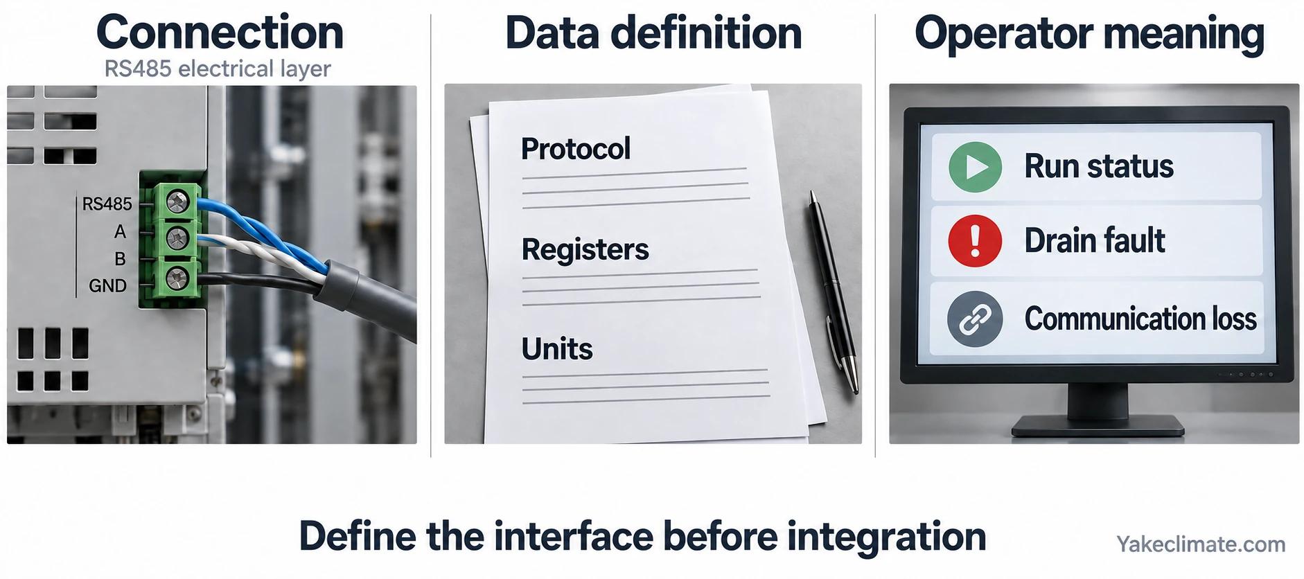
The project should first decide what operators need to know and what the wider system is allowed to control.
Define the Operating Functions
Typical functions can include:
- local automatic control;
Not every unit provides every function. The approved equipment configuration and interface documentation determine what is available.
Environmental Data
Possible monitored values include:
- internal air temperature;
- relative humidity;
- calculated dew point;
- a separate surface temperature;
- control setpoint;
- start and stop thresholds;
- trend data before and after a door or ventilation event.
If condensation prevention is the purpose, dew point and the coldest relevant surface are more directly useful than RH alone. The BMS/EMS trend should make it possible to reconstruct whether the surface approached the dew point.
Equipment-State Data
An ESS environmental-control record may include:
- device availability;
- running/stopped;
- operating mode;
- fault code;
- hours run;
- fan or compressor state;
- water-level or drain-pump state;
- sensor health;
- communication health.
This supports diagnosis. A rising humidity trend means something different when the unit is commanded off, running normally, in temperature protection, or unable to drain.
RS485 Is Not the Whole Specification
An RS485 interface review should identify:
- two-wire or four-wire arrangement;
- isolation and grounding;
- termination and biasing;
- baud rate, parity and stop bits;
- device addressing;
- protocol, commonly but not automatically Modbus RTU;
- register addresses and data types;
- scaling and units;
- read/write permissions;
- polling interval and timeout;
- exception and communication-loss handling;
- approved cable and topology.
The official Modbus serial-line guidance describes a bus topology and electrical implementation principles. Project wiring should follow the selected device documentation and system-network design.
Read-Only or Remote Control
Read-only monitoring is simpler and reduces the risk of an external command interfering with local environmental protection.
If remote write access is required, define:
- which system has authority;
- permitted setpoint range;
- local/remote priority;
- behaviour on communication loss;
- whether safety or equipment-protection limits override commands;
- event logging;
- cybersecurity and access control;
- fallback after controller restart.
A remote “off” command should not silently leave the enclosure outside its environmental limits. The expected behaviour must be agreed by the system owner.
Cabinet Dehumidifier Alarm and Fault Signals
An alarm list becomes useful when every signal has an operational meaning, a responsible response, and evidence that the displayed state matches the equipment state. They describe what the operator should be told; the approved equipment configuration determines which functions are actually available.
| Alarm | What it should tell the operator |
|---|---|
| High dew point or humidity | Reports that the defined monitored point meets the configured dew-point or humidity-alarm condition |
| Sensor fault | The control input is missing or implausible |
| Drain/high-water fault | Water removal may be blocked even if the drying element runs |
| Temperature protection | Reports the selected device’s defined temperature-limit or protection state; verify the configured response separately |
| Device fault | Reports a device fault requiring investigation against the selected device’s fault definition |
| Communication loss | The BMS/EMS no longer has current device data |
| Maintenance due | Inspection or service is required |
Read alarm state and input quality separately
In the OPC UA Part 9 model, active and inactive describe whether the condition exists or has returned to normal. Acknowledgement does not prove recovery. An optional latched state requires reset even after the triggering value returns to normal. Uncertain input data makes the dependent condition questionable. These distinctions illustrate questions to resolve; they do not imply OPC UA support in a cabinet.
| Contract field | Per-signal question |
|---|---|
| Identity and definition | Which cabinet, point, contact/register, firmware meaning, and data type are being referenced? |
| Trigger and timing | What condition activates it, and what delay or hysteresis applies? |
| Indication and response | What appears locally and remotely, and what response is required? |
| Ownership and authority | Who investigates, who may acknowledge or reset, and who controls the actuator or enable? |
| Records and acceptance | Which configuration, timestamp/history, and point-to-point evidence proves the intended behavior? |
Delay and hysteresis should prevent nuisance messages without hiding a real transition. They must be recorded with the signal definition rather than treated as universal defaults.
Hand off and verify the interface
For every approved signal, record expected local and remote indication, timestamps, history, clearing and restart behavior, and communication-loss reporting. Verify interpretation against the approved contact/register and firmware definition. Retain the point list and acceptance evidence. An absent alarm does not establish a healthy cabinet. Assign responsibility for the agreed response and approval; do not invent default failure actions.
Control Coordination
The dehumidifier may operate alongside:
- enclosure cooling;
- required ventilation;
- anti-condensation heating;
- gas detection;
- fire and safety systems;
- door switches;
- site-level energy management.
Define priority. Safety functions take precedence. The environmental control should know when a ventilation or door event has increased the moisture load, but it must not prevent a required safety action.
Cooling and dehumidification can also compete. A poorly coordinated sequence may overcool surfaces, cycle equipment unnecessarily or cause the dehumidifier's heat to be removed immediately by the air conditioner.
Data Worth Trending
For commissioning and operations, useful trends include:
- air temperature;
- RH and dew point;
- coldest-surface temperature where measured;
- dehumidifier run status;
- water or drain status;
- cooling and ventilation status;
- door status;
- alarm history;
- outdoor dew point.
These traces allow the team to answer:
- Did the unit run before the event?
- Did ventilation bring in humid air?
- Did a cold surface fall below dew point?
- Did the drain fail while the unit continued running?
- Did recovery meet the agreed time?
Commissioning the Interface
Use a point-to-point checklist rather than confirming only that “communication is online.”
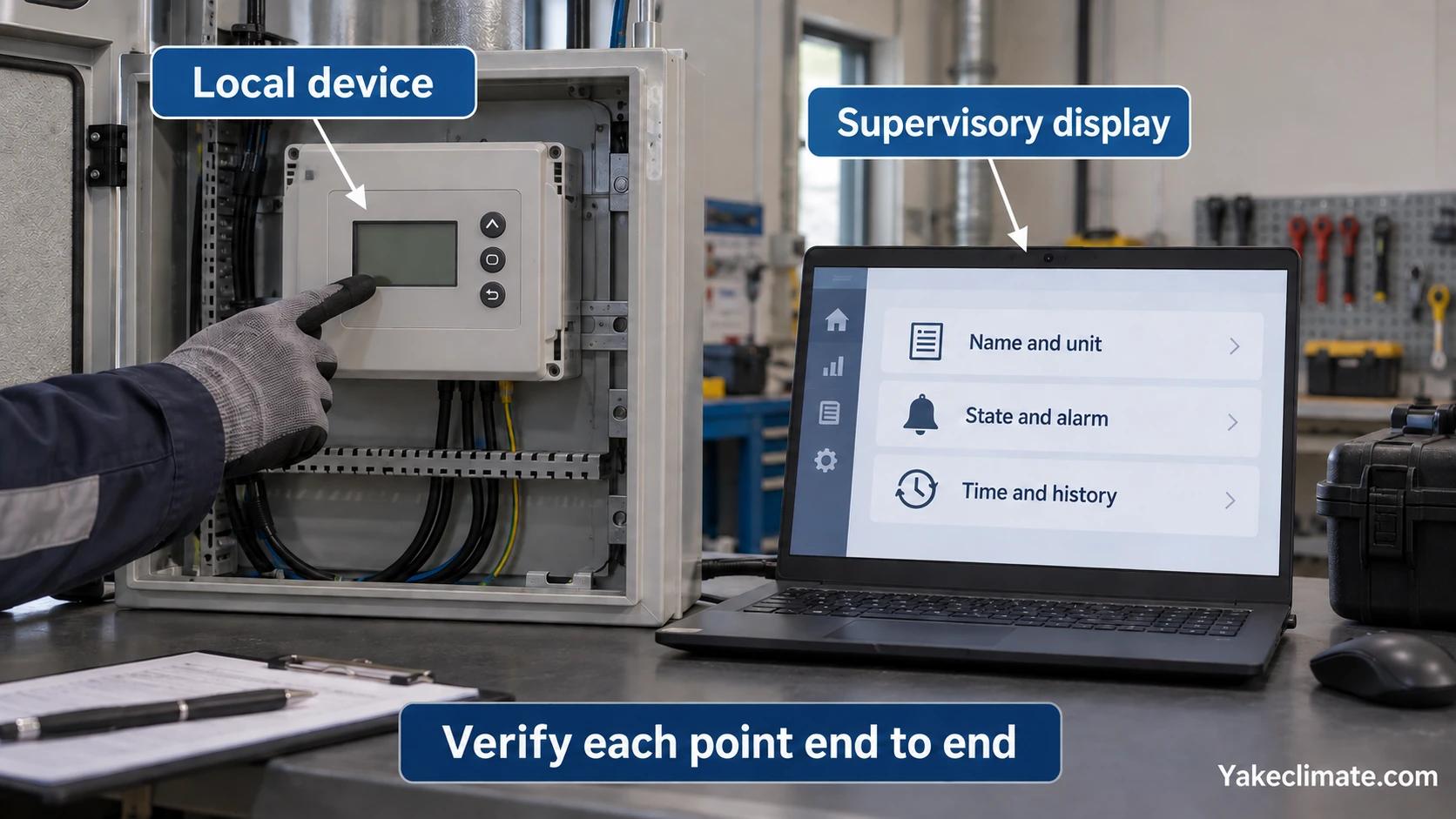
For each point:
- verify the displayed name and unit;
- compare the value with the local display or reference instrument;
- force or safely simulate the state;
- confirm alarm priority and delay;
- confirm timestamp and event history;
- test communication loss;
- test restart and fallback;
- record register version and firmware where applicable.
Remote write commands require an additional approved test of limits, priority and loss-of-communication behaviour.
Interface Document to Request
Before approval, request:
- wiring diagram;
- terminal definition;
- protocol and communication settings;
- register map with version;
- units, scaling and data types;
- supported commands;
- alarm list;
- communication-loss behaviour;
- firmware or configuration dependency;
- commissioning procedure.
Do not copy a register map from another model or firmware version without confirmation.
Product Selection and Interface Fit
Choose the environmental equipment first against moisture load, temperature range, airflow, drainage and mounting. Then confirm that the required interface is available in that exact configuration.
Discussing a Control Interface
Yakeclimate designs and manufactures industrial dehumidification equipment for complex climate applications, with a focus on agriculture and energy projects.
We co-develop application-specific dehumidification equipment around the operating conditions, interfaces, and integration requirements of the wider project or system.
Review the energy-storage equipment family or contact Yakeclimate with the point list, protocol requirements and cabinet drawing.
FAQ
Frequently Asked Questions
Does RS485 mean the dehumidifier will work with any BMS or EMS?
No. RS485 is an electrical serial layer. Compatibility also requires matching protocol, settings, addressing, register map, data formats, alarm meanings and command behaviour.
Which dehumidifier points should be monitored?
Monitor the approved point list: run status, common fault, the environmental value used for control, sensor health and drain/high-water status where relevant. Add other points only when the maintenance or diagnostic task requires them.
Should the BMS control the dehumidifier setpoint?
Only when remote write authority, limits, local/remote priority, communication-loss fallback and cybersecurity have been agreed. Read-only monitoring is simpler where local automatic control is sufficient.
Why monitor drain status separately?
A unit may continue to run while a blocked line or failed pump prevents water discharge. Drain or high-water status helps identify a drainage problem for investigation; it does not diagnose or exclude a drying-element fault.
What should happen if communication is lost?
The project should define a safe and reliable local fallback, alarm and recovery behaviour. It should not be left to an unstated default.
How is the interface commissioned?
Verify every point against the local device, safely simulate states and alarms, test units and scaling, test communication loss and restart, and record the register-map and firmware versions.
References
- Modbus Organization: Introduction to Modbus
- Modbus over Serial Line Specification and Implementation Guide
- Modbus Application Protocol Specification
