
Commissioning a BESS humidity-control device means proving more than “the unit turns on.” The installed system must move air through the intended zone, remove moisture under the relevant condition, drain safely, report useful status and recover after a defined moisture event.
The checklist below is a framework. The final procedure must follow the approved equipment manual, project drawings, battery-system requirements, electrical safety rules and site commissioning plan.
1. Confirm the Design Basis
Before testing, collect the approved inputs:
- controlled air boundary and volume;
- site temperature and humidity range;
- target RH, dew point or surface margin;
- coldest relevant surfaces;
- ventilation and leakage assumptions;
- door-opening condition;
- normal, standby and shutdown states;
- required recovery time;
- available electrical supply;
- drainage route;
- BMS or EMS point list;
- maintenance and access requirements.
If these inputs are missing, commissioning can verify device operation but cannot prove that the environmental requirement is suitable.
2. Check Documents and Equipment Identity
Record:
- project and cabinet identifier;
- manufacturer, model and serial number;
- hardware and controller version;
- electrical rating;
- declared operating range;
- capacity rating and test condition;
- drawings and revision;
- manual and wiring diagram;
- approved deviations;
- calibration certificates where required.
Confirm the installed unit matches the approved submittal. A capacity value without its rating condition is incomplete.
3. Inspect Installation Before Power
Check:
- mounting position and support;
- service clearance;
- process-air inlet and outlet;
- duct and grille condition;
- separation of supply and return air;
- filters;
- cable glands and enclosure penetrations;
- protective earthing;
- electrical protection and isolation;
- condensate tray and drain;
- regeneration ducting for desiccant equipment;
- labels and access.
Remove packaging and transport restraints. Confirm that airflow is not blocked by batteries, wiring or site-installed panels.
4. Verify the Drainage System
Where the equipment produces liquid condensate:
- inspect pipe size, fall and connection;
- confirm the hose is not kinked or lifted above the permitted route;
- check traps, vents or backflow arrangements required by the design;
- consider freezing conditions;
- perform a safe water or pump test;
- verify high-water or blocked-drain alarm where provided;
- inspect for leaks after operation.
Do not discharge water onto electrical equipment, access routes or an uncontrolled part of the enclosure. Review the battery-cabinet condensate drainage guide for drain routing, pressure, backflow and termination considerations.
For desiccant equipment, verify that warm moist regeneration exhaust is routed outside the protected air boundary and cannot recirculate.
5. Verify Sensors
For every environmental sensor:
- confirm identifier and location;
- check mounting and airflow exposure;
- compare with a traceable reference where required;
- confirm units and scaling;
- verify plausible temperature and humidity;
- calculate or confirm dew point;
- check surface-temperature sensors;
- test sensor-failure alarm.
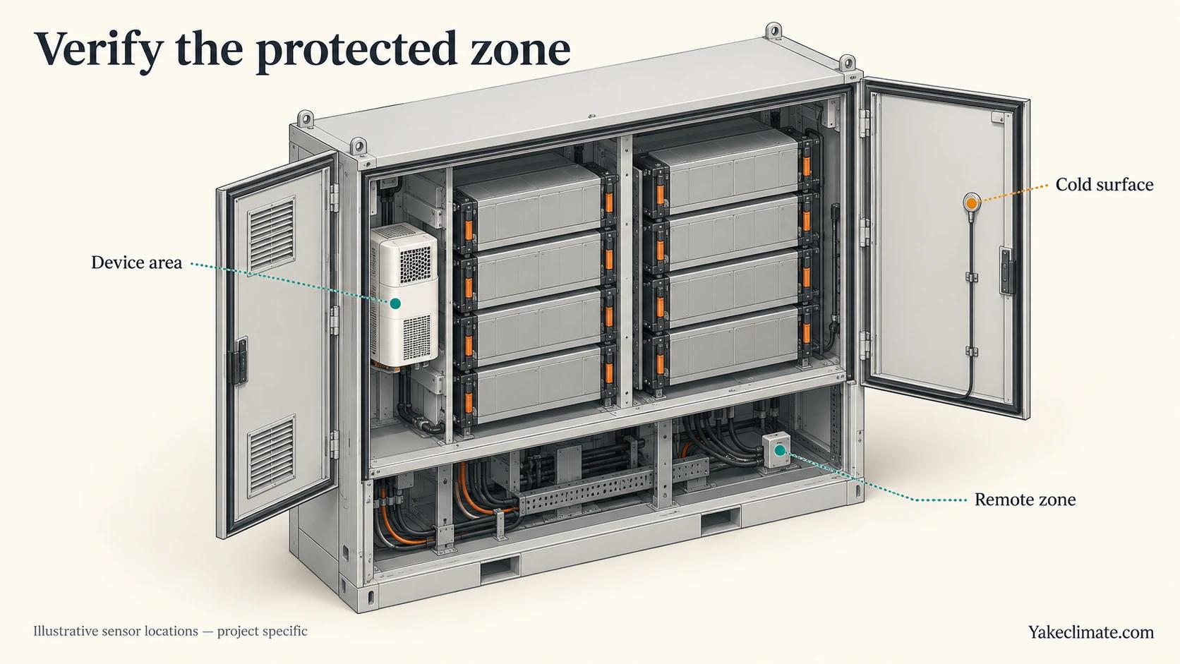
One sensor near the device is not enough to prove remote-zone performance. Use temporary points at credible cold surfaces and poorly mixed compartments.
6. First Power and Local Operation
Follow the manual and site safety procedure. Confirm:
- normal startup;
- controller display and configuration;
- fan direction and airflow;
- compressor, pump, heater or rotor operation as applicable;
- abnormal noise or vibration;
- current and voltage within approved limits;
- local start/stop;
- setpoint adjustment within permitted range;
- restart after controlled power interruption;
- local fault indication.
Do not force operation outside the model's stated temperature and humidity range merely to complete a test.
7. Confirm Airflow Reaches the Protected Zone
Measure or demonstrate:
- process-air quantity where specified;
- supply and return route;
- absence of major bypass;
- delivery to the cabinet base, cable chamber or remote compartment;
- pressure effect on doors, vents and safety ventilation;
- no short circuit between dry-air supply and return.
Smoke visualisation or other airflow tests must be approved for the electrical environment. Use safe methods and site procedures.
8. Test Local and Remote Controls
Verify every approved function:
| Function | Test evidence |
|---|---|
| Enable/disable | command, response and state |
| Setpoint | permitted range, scaling and readback |
| Local/remote | authority and indication |
| Run status | agrees with physical operation |
| Fault reset | cause removed and state restored |
| Communication loss | local fallback and alarm |
| Restart | state after power recovery |
| Interlock | response to door, HVAC or ventilation signal if specified |
RS485 alone does not define the protocol or register map. Test the project point list end to end. For cabinet identity, common control states and alarm meanings, use the multi-cabinet controls and alarms guide when preparing the point list.
9. Test Alarms
Use approved test methods for:
- high humidity or high dew point;
- sensor failure;
- fan, compressor, pump, heater or rotor fault where available;
- high water or blocked drain;
- communication loss;
- power failure;
- filter or service alarm where available.
Record trigger, delay, local indication, remote message, reset and operator action. Do not create unsafe fault conditions to prove an alarm.
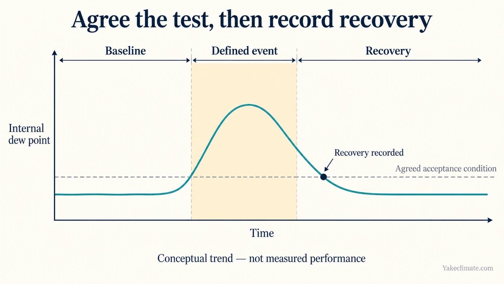
10. Establish a Baseline Trend
Before applying a moisture event, trend:
- internal temperature, RH and dew point;
- outdoor or surrounding-air condition;
- relevant surface temperatures;
- device run state;
- BESS operating state;
- door and ventilation status;
- condensate or drain status.
Use a common clock. The baseline should be long enough to show normal cycling and stable sensor behaviour.
11. Validate Environmental Recovery
Define a safe and representative event, such as:
- a controlled service-door opening;
- a planned ventilation period;
- transition from load to standby;
- startup after a documented shutdown;
- a naturally occurring high outdoor-dew-point period.
Record:
- starting condition;
- event duration;
- peak internal dew point;
- minimum cold-surface temperature;
- minimum surface-to-dew-point margin;
- device response;
- time to recover to the acceptance condition;
- conditions in remote zones.
The acceptance criterion must be agreed before the test. Do not create moisture, disable safety systems or open live electrical equipment without an approved method.
12. Test Operating States
Where applicable, confirm humidity-control behaviour during:
- charging;
- discharging;
- standby;
- maintenance;
- shutdown;
- loss and recovery of auxiliary power;
- local/manual mode;
- communication failure.
State which functions remain active and which alarms are still available.
13. Record Exceptions and Corrective Actions
For every failed or incomplete check, record:
- affected cabinet and device;
- observed condition;
- expected condition;
- immediate safe action;
- responsible party;
- correction;
- retest result;
- remaining limitation.
Do not close an item with “adjusted” or “fixed” alone. Keep the measured result.
14. Handover Package
The final record should contain:
- approved drawings and revisions;
- equipment list and serial numbers;
- configuration and point list;
- sensor map;
- alarm and interlock test;
- drainage test;
- baseline and recovery trends;
- photographs;
- open items;
- maintenance plan;
- spare-parts list;
- training and contact information;
- acceptance signatures.
Discussing Commissioning Requirements
Yakeclimate designs and manufactures industrial dehumidification equipment for complex climate applications, with a focus on agriculture and energy projects.
We co-develop application-specific dehumidification equipment around the operating conditions, interfaces, and integration requirements of the wider project or system.
Explore energy-storage dehumidifiers, review battery-room ventilation or contact Yakeclimate with the equipment schedule, point list and acceptance condition.
FAQ
Frequently Asked Questions
Is a successful startup enough for acceptance?
No. Startup proves basic operation. Acceptance should also verify airflow, sensors, drainage, alarms, communication and environmental recovery under an agreed condition.
Must every cabinet be tested?
Identity, installation, controls, alarms and drainage should be checked according to the project quality plan. Any sampling approach for performance tests must be agreed and justified.
How is moisture-removal performance verified?
For installed-system acceptance, record entering conditions, internal dew point, equipment operation, drainage and recovery across the protected zones against the agreed project test basis. These observations do not by themselves measure rated equipment moisture-removal capacity. Verifying that rating requires a separate quantitative test of water removal over a defined period under the specified entering-air temperature, humidity and other rating conditions, using the agreed measurement method. Keep the capacity test conditions and results distinct from site recovery and drain-function records.
Should a door-opening test always be used?
Only when it is safe and representative. The project may select another event, such as ventilation, standby transition or naturally humid weather.
What happens if seasonal conditions are unavailable?
Complete functional testing and document a seasonal verification plan with trigger conditions, responsibilities and acceptance criteria.
Who approves the commissioning result?
The responsible project parties should be defined in the commissioning plan. Equipment suppliers can support device checks, while system acceptance remains with the authorised project team.
