
A 20 ft or 40 ft BESS container does not have a standard dehumidifier capacity. Container length describes the outer boundary, not the moisture load. Two containers of the same size can require very different equipment because their free air volume, ventilation, door use, internal temperature, climate and dew-point target are different.
Reliable sizing begins with a moisture balance at the project condition and a capacity check against the dehumidifier's rated performance.
What the Calculation Is Trying to Do
The environmental objective should be stated before equipment is selected.
For condensation prevention:
target internal dew point ≤ coldest relevant surface temperature − agreed margin
The equipment must remove enough water to hold that target during the defined operating condition and recover after credible transient events.
The total load can include:
air leakage + required ventilation + door openings + wet materials + people/service + process sources + initial recovery
Not every project has every term. The calculation should show which terms were included and which were excluded.
20 ft and 40 ft Are Not Capacity Classes
The same nominal container can have:
- different internal clear dimensions;
- different battery and inverter layouts;
- different remaining free air volumes;
- different insulation and thermal bridges;
- continuous, intermittent or no routine ventilation;
- different air-conditioning arrangements;
- different service-door schedules;
- different climate exposure;
- a single aisle or several separated air zones.
A 40 ft container may have a lower moisture load than a smaller enclosure if it is better sealed and kept closed. A 20 ft unit with humid continuous ventilation can have a much larger load.
Container dimensions are still necessary, but they are only the starting geometry.
Input 1: Free Air Volume and Air Zones
Use the volume of air that can actually circulate, not the empty shell volume.
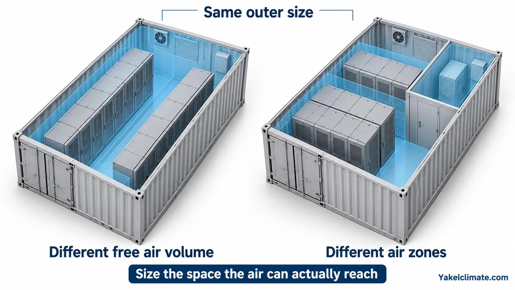
Subtract or account for:
- battery racks;
- PCS, transformers and switchgear;
- ducts and plenums;
- internal walls and service compartments;
- cable trays and large auxiliary equipment.
Then identify separate air zones. A unit installed in the service aisle may not treat a sealed electrical compartment. The sizing review should match each dehumidifier to the volume and airflow path it actually controls.
Input 2: Outdoor Design Conditions
Provide coincident temperature and humidity or outdoor dew point for the sites under review. Do not combine the annual maximum temperature with an unrelated annual maximum RH; that can create a condition that never occurs.
For a repeated product, define:
- the reference site;
- the most humid deployment site;
- the lowest-temperature site;
- coastal or industrial contamination exposure;
- altitude if it materially affects equipment or airflow.
The highest outdoor dew point often sets the infiltration and ventilation moisture load. The lowest internal temperature often sets the condensation margin and equipment technology limit.
Input 3: Internal Temperature Profile
Record the internal range during:
- charge and discharge;
- standby;
- overnight operation;
- planned and unplanned shutdown;
- commissioning;
- maintenance with doors open;
- winter minimum;
- cooling-unit cycling.
Steady-state operating temperature is not enough. Many condensation events occur during transitions when surfaces and air change temperature at different rates.
Input 4: Air Leakage
Leakage can be described by:
- measured air leakage;
- an enclosure leakage test;
- a known pressure-equalisation path;
- an estimated air-change rate with a stated basis;
- a conservative scenario agreed by the project team.
Do not assume zero leakage because the enclosure has an IP or NEMA rating. Those ratings do not provide a moisture-load value.
For repeated deployments, leakage consistency between units may matter as much as the nominal design value.
Input 5: Required Ventilation
If ventilation is required, provide:
- flow rate;
- continuous, intermittent or event-triggered duty;
- intake air source;
- control trigger;
- operating duration;
- exhaust path;
- interaction with cooling and fire/safety controls.
Ventilation air can dominate the moisture load. Establish the safety or thermal ventilation requirement before finalising the dehumidifier.
Input 6: Door-Opening and Service Events
Door opening can replace a significant fraction of the internal air within minutes. Provide:
- number and size of doors;
- normal opening frequency and duration;
- expected outdoor conditions during service;
- whether equipment remains cold while the door is open;
- required recovery time after closure.
If the project needs rapid recovery after service, that transient can determine capacity even when steady leakage is small.
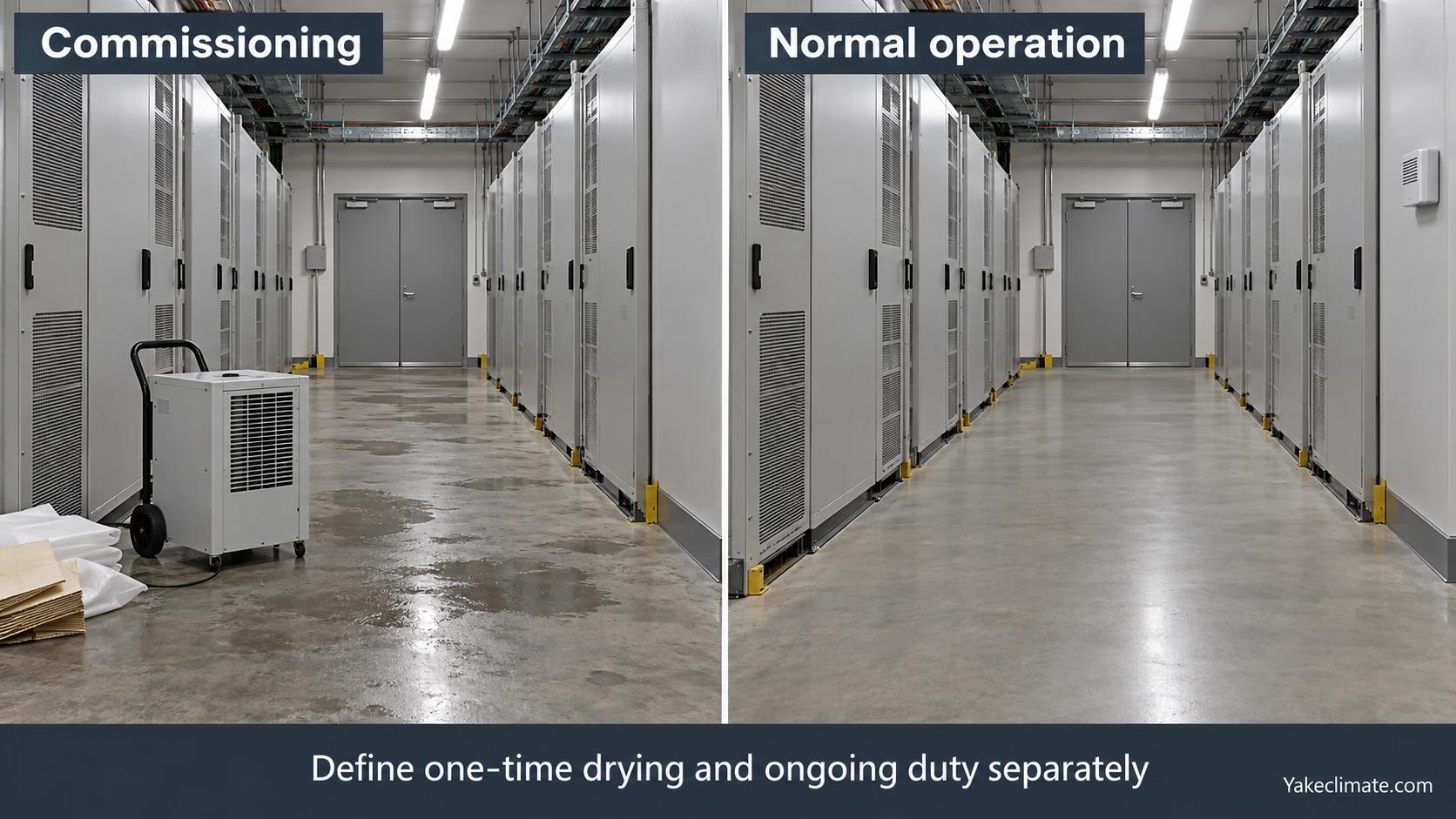
Input 7: Moisture Already in the Container
Commissioning loads may include:
- damp packaging;
- wet floors;
- water-based cleaning;
- moisture in insulation or filters;
- rain exposure during assembly;
- humid air trapped before sealing.
Decide whether the installed dehumidifier must perform this initial dry-down or whether the container will be dried by a separate commissioning process. Mixing the two duties can oversize every production unit to cover a one-time event.
Input 8: The Control Target
A target such as “below 60% RH” is incomplete unless the temperature range is known. For condensation control, define:
- the coldest relevant surface;
- expected minimum surface temperature;
- target internal dew point;
- control margin;
- acceptable recovery time;
- any customer or component environmental limit.
Where the customer specification is written in RH, calculate the corresponding dew point at the relevant temperatures and check it against the surface condition.
Input 9: Product Performance at Actual Conditions
Catalogue removal capacity is quoted at a stated test condition. Water removal generally decreases as the air becomes cooler or drier.
The selection review should compare:
- rated test condition;
- expected operating condition;
- minimum temperature;
- target dew point;
- required duty and recovery;
- manufacturer performance data available for the selected unit.
Do not divide the calculated litres per day by a nameplate value measured at a warmer, wetter condition and treat the result as complete.
Input 10: Installation, Drainage and Controls
Capacity is only useful if the unit can be integrated.
Confirm:
- mounting position and orientation;
- supply and return airflow;
- service clearance;
- power supply;
- gravity or pumped drain route;
- freezing and backflow risk;
- local and remote start/stop;
- run, fault and high-water signals;
- required communication and operating data;
- redundancy and failure response.
These constraints can eliminate an otherwise adequate unit.
A Practical Sizing Worksheet
| Field | Project value |
|---|---|
| Container type and internal clear dimensions | To be provided |
| Free air volume by compartment | To be provided |
| Site design temperature/RH or dew point | To be provided |
| Internal minimum/maximum temperature | To be provided |
| Coldest relevant surface | To be provided |
| Target dew point and margin | To be provided |
| Leakage or air-change basis | To be provided |
| Ventilation flow and duty | To be provided |
| Door-opening scenario | To be provided |
| Commissioning recovery requirement | To be provided |
| Drain route | To be provided |
| Power and control interface | To be provided |
| Redundancy and service interval | To be provided |
Unknown values should remain marked as unknown. They are questions for the project team, not gaps to fill with generic assumptions.
Verification After Selection
The selected arrangement should be checked by:
- reviewing the equipment performance at the expected conditions;
- confirming airflow reaches each controlled zone;
- testing drainage in installed orientation;
- verifying controls and alarms;
- logging internal dew point and cold-surface temperature during commissioning;
- recording recovery after a representative door or ventilation event;
- agreeing acceptance criteria before the test.
Discussing a BESS Container
Yakeclimate designs and manufactures industrial dehumidification equipment for complex climate applications, with a focus on agriculture and energy projects.
We co-develop application-specific dehumidification equipment around the operating conditions, interfaces, and integration requirements of the wider project or system.
Explore energy-storage dehumidifiers or contact Yakeclimate with the completed input worksheet.
FAQ
Frequently Asked Questions
What size dehumidifier does a 20 ft BESS container need?
There is no standard capacity from container length alone. Free air volume, outdoor dew point, internal temperature, leakage, ventilation, doors, target condition and performance at the actual operating condition are all required.
Does a 40 ft container need twice the capacity of a 20 ft container?
Not necessarily. Moisture load does not scale only with geometric volume. Air exchange, ventilation and door operation can dominate, while equipment layout changes the free air volume and air zones.
Should ventilation air be included in the load?
Yes. Use the established ventilation flow, operating duty and incoming moisture condition. In humid climates it can be the largest continuous load.
How should catalogue capacity be used?
Treat it as performance at the stated rating condition. Check or obtain performance at the expected project temperature and humidity. Capacity usually falls as air becomes cooler or drier.
Should commissioning dry-down be included?
Only if the installed unit is expected to perform it. A one-time wet commissioning condition may be handled separately so that every production unit is not sized for an event outside normal duty.
What should the acceptance test measure?
Measure internal dew point, cold-surface temperature, operating status, drainage and recovery under an agreed representative condition. Define the target and acceptance period before the test.
References
Related technical reading
Apply the sizing inputs to the intended configuration. Compare central and cabinet-level dehumidification and cabinet air, heat and moisture paths. For special operating conditions, retain the high-altitude calculation and equipment evidence and moisture-protection records during seasonal shutdown with the project review.
