
A humidity reading is only representative of the air around the sensor. It does not prove that every compartment, cable chamber or metal surface in a battery energy storage system is protected from condensation.
Useful monitoring combines three measurements:
- air temperature and humidity, used to calculate dew point;
- temperature at credible cold surfaces;
- operating and environmental events that explain why the values changed.
The objective is to measure where moisture enters, where air is controlled and where condensation would appear first.
Start with the Condensation Condition
Condensation becomes possible when:
local surface temperature ≤ local air dew point
This relationship determines what must be measured. A sensor placed in warm return air may report acceptable relative humidity while a cable gland, roof panel, cold plate or cabinet base is below dew point.
Condensation Risk in Battery Enclosures explains why relative humidity alone is not a complete condensation alarm.
Map the Enclosure Before Selecting Sensor Locations
Divide the equipment into air and thermal zones. Typical zones include:
- battery module compartments;
- power-conversion or control compartments;
- cooling-unit supply and return paths;
- cable chambers and trench connections;
- areas beside service doors;
- roof, floor and external-wall zones;
- separated cabinets within one container;
- spaces behind panels or components with restricted airflow.
Mark moisture-entry paths, heat sources, cooling surfaces, airflow routes and credible cold points. Sensor locations should follow this map rather than a uniform spacing rule.
Air Sensors: Measure the Air That Matters
Place air temperature and humidity sensors where they can answer a defined question.
| Location | Question answered | Common mistake |
|---|---|---|
| Controlled-zone return air | What condition reaches the environmental-control system? | Treating return air as the whole enclosure |
| Near a door or leakage path | How quickly does outdoor moisture enter? | Mounting so close that the sensor only sees a short local jet |
| Cable chamber or cabinet base | Is humid air entering from below? | Relying on a room-level sensor |
| Remote or poorly mixed compartment | Does that zone recover after a moisture event? | Assuming airflow reaches behind equipment |
| Outdoor reference point | What moisture content is available to enter? | Using outdoor RH without temperature |
Avoid direct contact with walls, condensate spray, radiant heat, strong supply-air jets and component exhaust unless that local condition is the intended measurement.
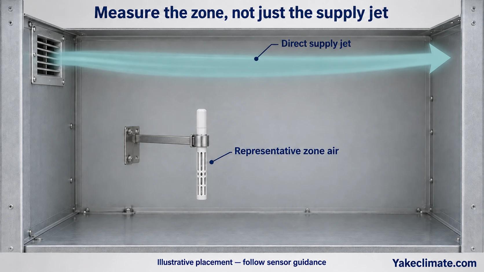
Allow space around the probe and follow the sensor manufacturer's mounting and response-time guidance.
Surface Sensors: Find the First Likely Wet Point
Air dew point must be compared with surface temperature. During diagnosis and commissioning, attach surface sensors to representative cold points such as:
- roof underside and shaded external wall;
- cabinet base above a cool foundation or cable trench;
- cable gland plate and large metal penetrations;
- refrigerant or coolant pipes;
- cooling coils, cold plates or nearby metalwork;
- structural thermal bridges;
- heavy components that warm more slowly after startup.
Good thermal contact matters. A loosely attached sensor that is affected by surrounding air may not represent the actual surface. The selected sensor, adhesive or mounting method must also suit the electrical, temperature and maintenance conditions.
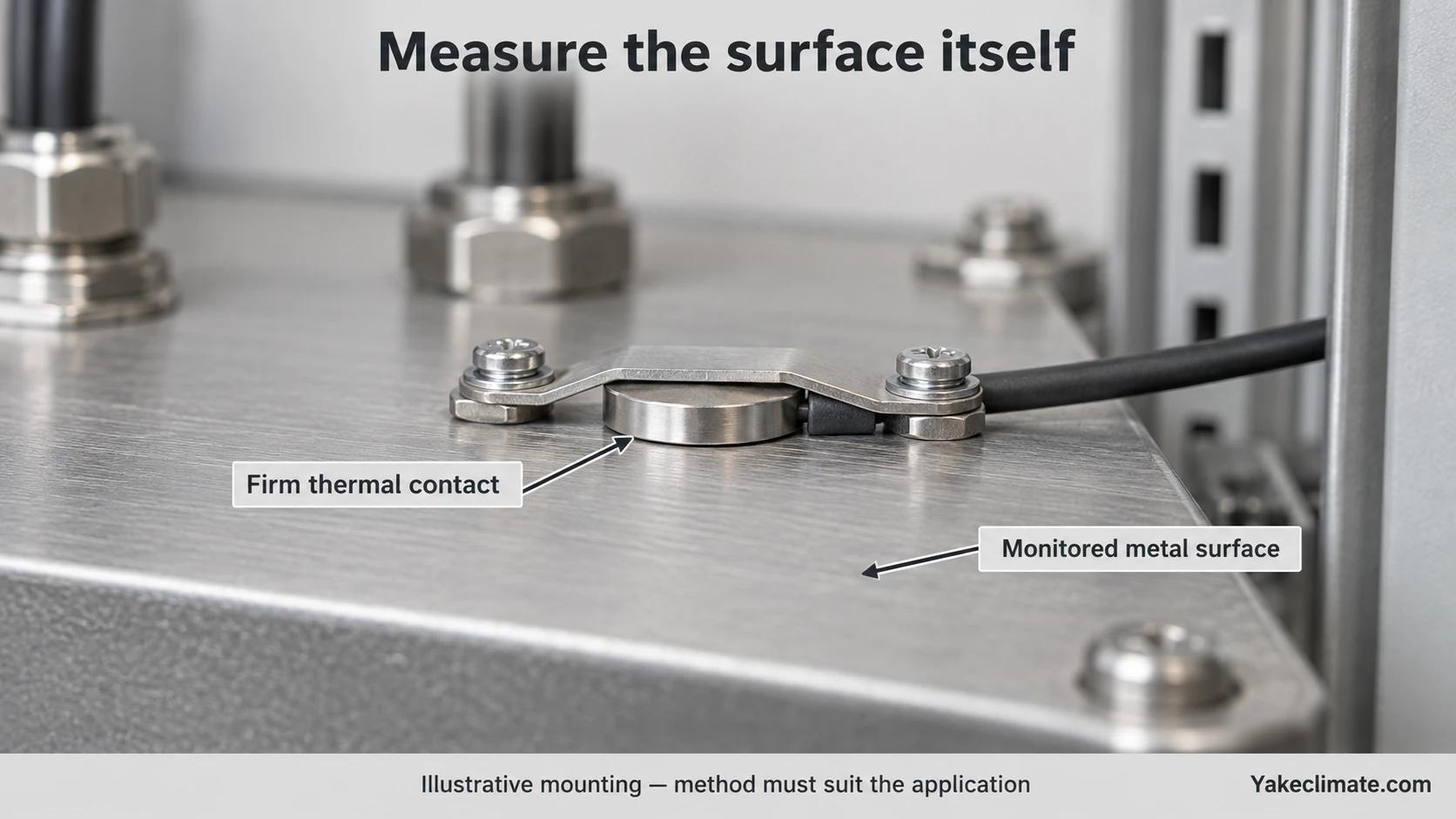
Infrared inspection can help locate cold areas, but emissivity, reflections and line of sight can affect readings. Use contact sensors to trend critical points through operating cycles.
Use More Than One Point When the Air Is Not Well Mixed
One air sensor may be adequate for routine control in a small, well-mixed and validated zone. Additional points are justified when:
- partitions create separate air volumes;
- supply air does not reach the cabinet base;
- the system has several doors or outside-air paths;
- modules or auxiliaries create different heat loads;
- condensation has appeared away from the control sensor;
- a cable trench has a different dew point from the room;
- one controller serves several cabinets.
The final permanent sensor count should follow the risks found during commissioning. Temporary commissioning sensors can be more numerous than the permanent control points.
Add an Outdoor Reference
Outdoor relative humidity cannot be interpreted without outdoor temperature. Together they provide outdoor dew point, which helps estimate the moisture introduced through ventilation, leakage and door opening.
Mount the outdoor reference where it is:
- shaded and protected from direct rain;
- away from hot exhaust or condenser discharge;
- exposed to representative site air;
- accessible for inspection and calibration.
Comparing outdoor and internal dew point also helps distinguish internal moisture release from external humid-air entry.
Place Sensors Around the Environmental-Control Equipment
For a dehumidifier or air-conditioning system, temporary sensors at inlet and outlet can show whether the equipment is changing air conditions as expected. Record:
- entering and leaving air temperature;
- entering and leaving dew point or humidity;
- run status and operating mode;
- condensate production or drain status;
- fan and compressor cycling;
- alarm state.
These values should be interpreted with airflow and time. A large humidity change in a small recirculation loop does not prove that the remote cabinet zone is drying.
Time Alignment Is as Important as Location
All relevant data should use a common clock. Align:
- air temperature and humidity;
- calculated dew point;
- cold-surface temperatures;
- charge, discharge and standby state;
- cooling, heating and dehumidifier status;
- door contacts;
- ventilation commands;
- alarms;
- outdoor conditions.
Without time alignment, a brief door event or control transition may look unrelated to condensation found later.
Choose a logging interval that can capture the expected event. A slowly sampled trend may miss a short cooling cycle; a very fast interval may create unnecessary data without improving decisions. Define the interval in the commissioning plan.
Response time is not the logging interval
Faster recording does not make a probe respond faster. Ask how the response specification was measured, what fraction of a change it represents and which temperature and humidity conditions apply. A smooth trend alone cannot establish that a brief event was captured.
Check the assembled instrument
Ask for response evidence for the assembled probe in its intended housing and airflow arrangement. Record the response definition, test conditions and both humidity and temperature behavior alongside timestamped event records. Check whether the installed instrument can follow the event before choosing a logging interval. Any enclosure modification needs the equipment manufacturer’s approval.
Define Alarms Around a Margin, Not Only a Fixed RH
A dew-point margin alarm compares the coldest relevant surface with local dew point:
dew-point margin = surface temperature − air dew point
The project team should define:
- which surface is used;
- which air sensor represents the local moisture condition;
- warning and action thresholds;
- persistence time before an alarm;
- sensor-failure behaviour;
- response during standby or communication loss.
Do not apply a universal margin. The required value depends on measurement uncertainty, response time, equipment criticality and operating variability.
Worked example: read both temperature trends
In this hypothetical example, synchronized air and surface readings are assumed. Surface margin = cold-surface temperature − local air dew point; A–D are sequence labels, not time intervals.
| Sequence | Air dew point | Cold surface | Surface margin |
| A | 12°C | 18°C | +6°C |
| B | 10°C | 13°C | +3°C |
| C | 12°C | 13°C | +1°C |
| D | 14°C | 13°C | −1°C |
The margin narrows from A to B although dew point falls, because the surface cools more. It narrows again from B to C as dew point rises while the surface stays at 13°C. At D, the selected surface is below the local dew point. The NWS dew point definition describes dew point as the temperature reached by cooling air to saturation at constant pressure and moisture content; the table’s surface margin is different from air-temperature dew point depression. These numbers establish neither cause nor observed wetness, and provide no universal alarm threshold or safe positive margin. Interpretation needs valid paired readings and project-approved uncertainty and alarms.
Calibration, Access and Replacement
A useful sensor must remain trustworthy. Record:
- sensor model and range;
- stated accuracy and operating limits;
- installation location and identifier;
- calibration or verification date;
- replacement procedure;
- access restrictions;
- controller scaling and register mapping.
High-humidity exposure, contamination, condensation on the probe and chemical vapours can affect measurement performance. Select the instrument for the actual application and follow its maintenance guidance.
Read calibration evidence by condition
A useful calibration report ties each result to requested temperature and relative humidity points under stable conditions. NIST describes recording reference measurements and device readings at each point, then reporting the tested instrument, reference or generated value, indicated value, and uncertainty. The sample report makes clear that its results apply only to the tested item. Use those fields to compare a supplier claim with the conditions your enclosure requires; a steady laboratory calibration does not, by itself, verify accuracy after installation in a cabinet. NIST calibration procedure and sample report
Commissioning Sequence
Use a repeatable sequence:
- inspect the enclosure and mark air zones, entry paths and cold surfaces;
- install temporary air, surface and outdoor reference sensors;
- verify sensor identity, time base and plausible readings;
- record normal load, standby, shutdown and restart;
- include a controlled door or ventilation event where safe;
- confirm the environmental-control equipment reaches remote zones;
- review the minimum surface-to-dew-point margin;
- adjust airflow, sealing, control logic or equipment where required;
- repeat the relevant operating and weather condition;
- retain the final sensor map and acceptance trends.
Information to Prepare
For a monitoring review, provide:
- enclosure and compartment drawings;
- airflow route and environmental-control layout;
- known moisture-entry paths;
- minimum expected surface temperatures;
- outdoor temperature and humidity range;
- operating and standby sequence;
- door-opening and maintenance pattern;
- existing BMS or EMS points;
- required alarms and data-retention period;
- calibration and maintenance requirements.
Unknown values can be measured during a site survey or commissioning period. They should not be replaced with an assumed “typical” sensor layout.
Discussing Dew-Point Monitoring
Yakeclimate designs and manufactures industrial dehumidification equipment for complex climate applications, with a focus on agriculture and energy projects.
We co-develop application-specific dehumidification equipment around the operating conditions, interfaces, and integration requirements of the wider project or system.
Review moisture control for electrical cabinets, explore energy-storage dehumidifiers or contact Yakeclimate with the sensor map, cold-surface locations and control requirements.
FAQ
Frequently Asked Questions
Where should the main humidity sensor be installed?
Place it in air that represents the controlled zone and is not distorted by direct supply air, a hot component, a cold wall or condensate. Confirm during commissioning that remote zones follow the same condition.
Is one temperature and humidity sensor enough?
Only when the volume is well mixed and testing shows that it represents the relevant zones. Separated compartments, cable chambers and remote cold points often need additional temporary or permanent monitoring.
Why measure surface temperature?
Condensation occurs on a surface, not at an average room value. Surface temperature shows whether a particular component is approaching the local air dew point.
Should a sensor be placed beside the door?
A door-area sensor can be useful for studying moisture entry, but it may not represent the whole enclosure. Use it as an event or boundary measurement and keep a representative control point elsewhere.
Can the BMS calculate dew point?
It can if it receives valid temperature and humidity data and uses an appropriate calculation. The input sensor range, accuracy, scaling and failure handling must be confirmed.
How often should sensors be calibrated?
Follow the sensor manufacturer's guidance and the project's quality and criticality requirements. Verification should also follow contamination, prolonged condensation, repair or implausible trends.
