
Moisture risk in a battery cabinet depends on the air, the temperature of exposed surfaces, contaminants and the equipment's operating limits. Condensation is one important failure route, but corrosion or insulation problems can also occur without visible droplets.
For example, a cabinet may remain dry at a given relative humidity while its surfaces are warm. If a local surface later cools below the dew point of the adjacent air, condensation becomes possible. This is a conditional design scenario, not a report of a measured battery installation.
Start by identifying the enclosure boundary, moisture sources and cold surfaces. Then distinguish the cabinet-level condensation question from the separate tasks of room safety ventilation and equipment sizing.
Sealed Electrical Enclosures Do Not Behave Like Rooms
A compact enclosure does not behave like a well-mixed room. Components, cooling hardware and the enclosure skin may be at different temperatures, while service openings and boundary leakage change the internal moisture condition.
Small free air volume can change temperature and moisture conditions quickly, but volume alone does not determine dehumidifier capacity. Moisture entry, internal generation, temperature, removal performance and recovery time all matter.
The enclosure skin, cells, electronics and cooling surfaces can differ in temperature. The coldest relevant surface for a particular operating state should be measured or supported by a validated thermal model; it cannot be inferred from the average cabinet air temperature alone.
For surface condensation, compare the local surface temperature with the dew point of the adjacent air.
Condensation Is One Moisture Failure Mode
Condensation becomes possible when a surface cools to or below the dew point of the air next to it. Relative humidity remains useful for specified material and equipment limits, while dew point and surface temperature describe the condensation margin.
The values below are illustrative air states at standard atmospheric pressure. They describe air dew point, not the temperature of every surface in an actual cabinet.
| Air condition | Approximate dew point | Interpretation |
|---|---|---|
| 25 °C, 60 % RH | ≈ 16.7 °C | A local surface near or below this value may condense |
| 35 °C, 50 % RH | ≈ 23.0 °C | A local surface near or below this value may condense |
| 30 °C, 80 % RH | ≈ 26.2 °C | A local surface near or below this value may condense |
At 35 °C and 50% RH, the example air has a dew point near 23 °C. If a local surface is at or below that temperature while the air moisture state persists, condensation is possible there. The rest of the cabinet may stay dry; actual risk depends on measured or validated local conditions.
Liquid films can contribute to corrosion or electrical leakage, especially where contaminants and energized surfaces are present. The prevalence and severity of field failures require installation-specific evidence; this article does not infer that most corrosion has this cause.
Why Sealed Enclosures Still Get Wet
A common assumption is that a high ingress-protection rating solves this. It does not, and the reason is worth understanding.
An IP rating classifies specified protection against solid objects and water ingress. It does not by itself establish the internal vapor balance or prevent condensation of moisture already inside. For the boundary and control implications, see why an IP-rated enclosure can still condense.
Temperature and pressure changes, gasket condition, cable penetrations, vents and service openings can exchange air across an enclosure boundary. Incoming air may add moisture, while later exchange or drying may remove it. Net moisture retention depends on both sources and sinks, not on the number of thermal cycles alone.
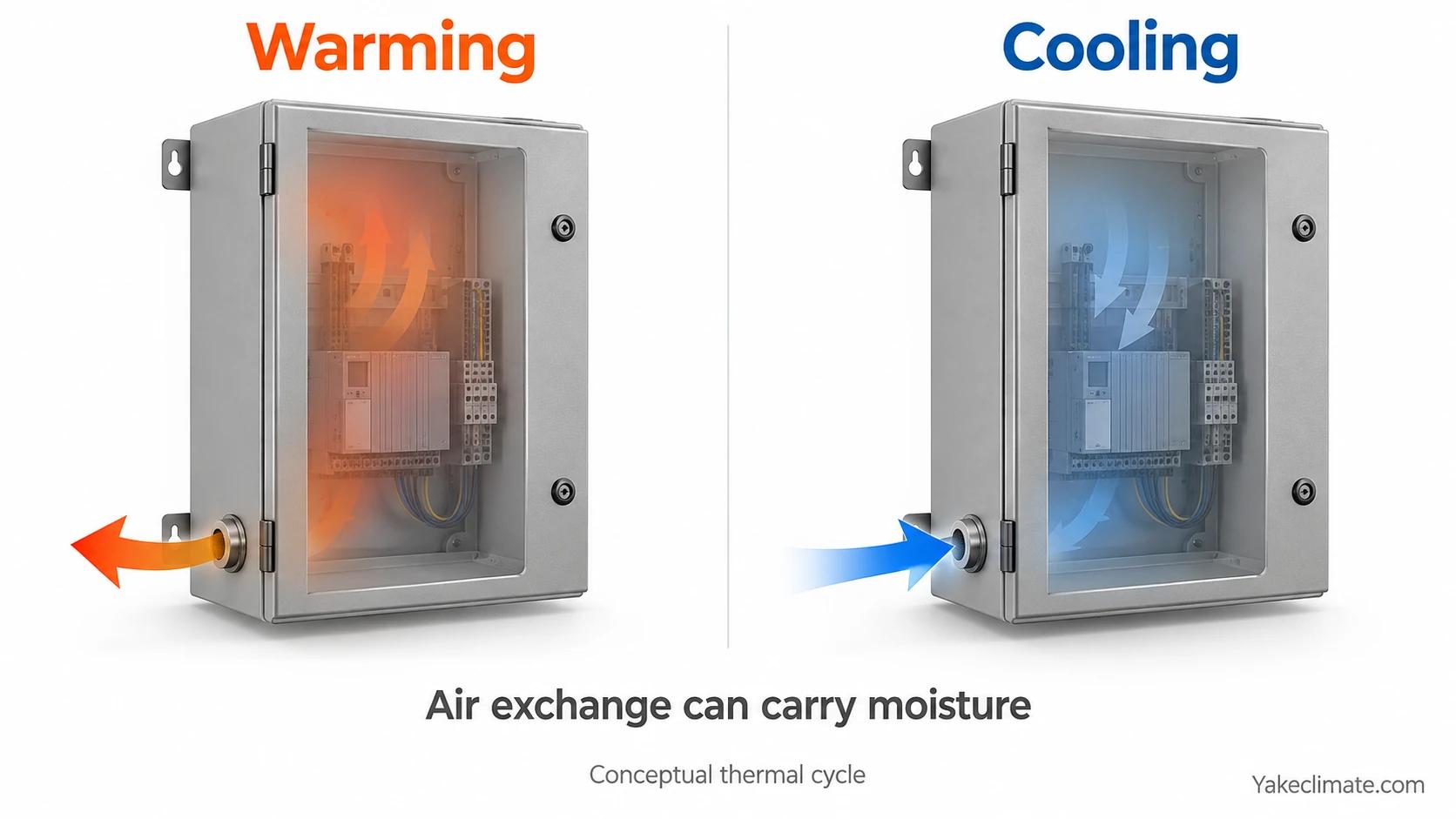
A cabinet can resist rain yet still face internal condensation if its air dew point exceeds a cold surface temperature. Check the actual boundary, leakage and drying paths before selecting a remedy; a higher IP label alone is not an internal humidity-control design.
What Moisture Actually Damages
Moisture may affect electrical and mechanical parts through more than one mechanism. The examples below are possible failure pathways, not evidence of their frequency in a particular fleet.
Insulation resistance and tracking. A liquid film across an insulating surface between conductors at different potentials creates a leakage path. Where the film carries dissolved contamination — salt in coastal sites, dust, flux residue — the leakage current is higher and can carbonise the surface, leaving a permanent conductive track that persists after the surface dries.
Electrochemical migration on printed circuit boards. BMS boards, contactor control boards and communication cards carry closely spaced conductors. Under bias and in the presence of a moisture film and ionic contamination, metal can migrate between adjacent conductors and form dendrites, which produce intermittent faults before producing hard shorts.
Corrosion at terminations. Busbar joints, lugs and terminals depend on stable electrical contact. Where corrosion products develop at a contact, resistance and local heating may increase and further degrade the joint. A real failure attribution requires contact-resistance and thermal evidence, load history, materials, contamination and inspection findings.
Connector fretting. Repeated micro-motion from thermal cycling and vibration, combined with an oxidising environment, degrades plated connector contacts over time.
Sensor and monitoring drift. Moisture may affect sensors, connectors or insulation-monitoring readings. Repeated alarms after a cold night are a reason to investigate, not proof of condensation. Compare the alarm record with local air dew point, suspected surface temperature, device self-diagnostics and the actual insulation condition.
These mechanisms can remain hidden until inspection or fault diagnosis. If a project needs a quantified risk estimate, use its materials, contaminants, temperatures, inspection record and test results.
Cabinet, Room and Container Are Three Different Design Problems
The phrase “battery humidity control” can refer to a compact cabinet, a dedicated battery room or a containerized system. Each has different air-exchange paths, cold surfaces, safety duties and service constraints; define the actual boundary before selecting equipment.
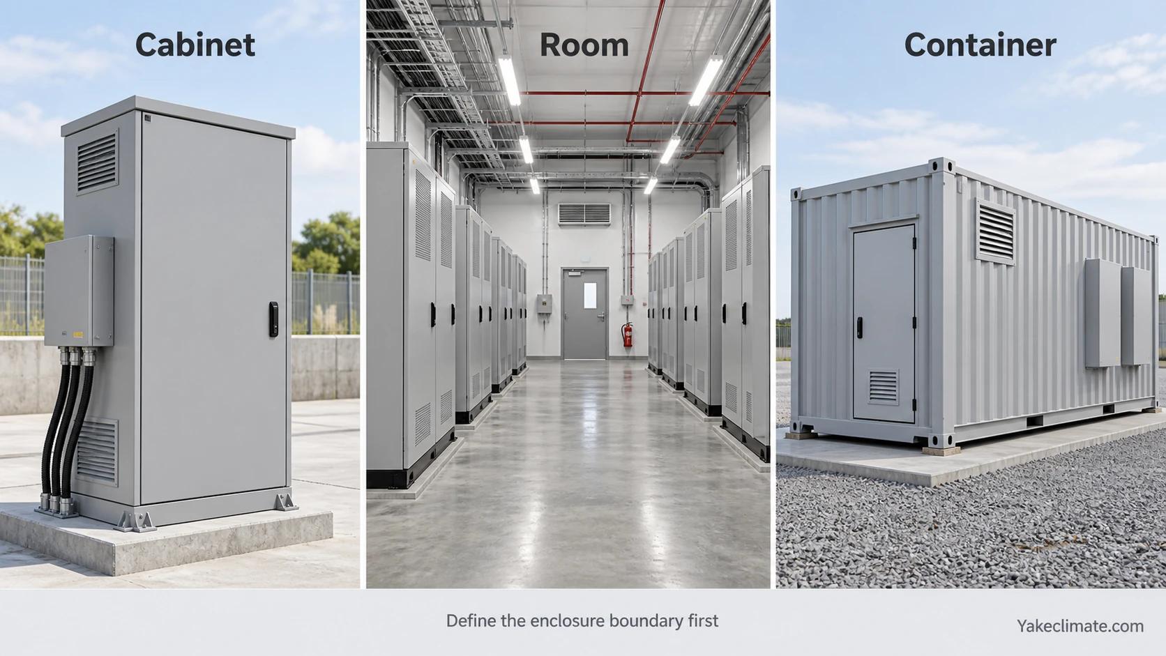
| Design boundary | Cabinet | Battery room | Container |
|---|---|---|---|
| Free space | Constrained by components | Building-scale occupied volume | Equipment and aisle volume |
| Moisture inputs to check | Leakage, vents and openings | Outdoor air, infiltration and people | Outdoor air, doors and internal sources |
| Cold surfaces to check | Skin, cooling hardware, local parts | Building envelope and equipment | Shell, ducts and cooling surfaces |
| Selection focus | Load, integration and service access | Airflow duty and room load | Airflow, shell and control sequence |
| Service model | May require planned access | Project-specific | Project-specific |
| Repeatability | May be standardized | Often site-specific | May be standardized |
A cabinet, room and container have different boundaries and service constraints. Selection starts with moisture load and operating conditions, then checks mounting, power, drainage, alarms and maintenance access. No format follows from free air volume alone.
Check each proposed unit against its verified performance at the project temperature and humidity, not a technology-wide rule. Product operating range does not by itself prove moisture-removal capacity at the coldest design condition.
Ventilation and Dehumidification Are Not Alternatives
Ventilation or gas management and environmental moisture control answer different design questions; neither can be assumed to satisfy the other.
The applicable battery-room or ESS safety design is set by the adopted code edition, battery technology, product test evidence, installation configuration and responsible engineer or authority having jurisdiction. This overview supplies no universal gas-ventilation rate or explosion-control prescription.
Dehumidification addresses an environmental moisture duty. Where the concern is surface condensation, the relevant comparison is air dew point versus cold-surface temperature; the project may also specify separate RH limits for equipment or materials.
Required safety airflow can introduce an outdoor-air moisture load. Whether it raises indoor dew point depends on the outdoor and indoor air states and the operating schedule. Establish safety airflow separately, then calculate the environmental duty it creates.
The relationship between the two, and how the required ventilation rate is established, is covered in detail in battery room ventilation and humidity control, which separates the safety case from the environmental case.
Use Dew Point for Condensation; Keep Other Humidity Limits
For condensation, compare air dew point with the coldest relevant surface. Also retain any RH limits required for corrosion, insulation, materials or equipment.
For illustration, 60% RH at 25 °C corresponds to a dew point near 16.7 °C; the same RH at 35 °C corresponds to a dew point near 26.2 °C. A fixed RH value therefore does not describe one fixed condensation margin across temperatures.
A project can set a fixed dew-point target below a validated minimum surface temperature, with a margin for sensor error and variation. A dynamic surface-referenced target needs measured surface inputs, verified controls and a tested operating sequence; it is not automatic in every dehumidifier.
- The coldest relevant surface temperature, measured in representative operation or supported by a validated thermal model.
- A project-specific margin that accounts for measurement uncertainty, local variation and control response.
Set the moisture-control target using those inputs and verify it under the relevant operating states. A fixed target and an adaptive target are different designs; neither should be claimed without a defined control sequence.
Sensor placement must represent the conditions the design is protecting. A warm-zone reading alone may miss a colder local surface.
For a worked surface-risk method and the evidence needed for a cold-surface estimate, see condensation risk in battery enclosures.
For Repeated Deployments, Verify the Operating Envelope
A repeated cabinet design may see different climates, contaminants and maintenance schedules. Verify the defined envelope for each deployment group instead of assuming one site represents every site.
This changes the environmental specification in three ways.
For multi-site alarm, service and control consistency, see multi-cabinet controls and maintenance.
Inputs for the Next Design Review
Record the boundary, site air states, cold surfaces, moisture sources, ventilation duty, required humidity limits and service constraints. The detailed worksheet belongs in BESS dehumidifier sizing inputs.
Mark unknown values as unknown. Test or measure the inputs that materially change the design before committing to equipment capacity or a control setpoint.
Discussing a Storage Project
Yakeclimate designs and manufactures industrial dehumidification equipment for complex climate applications, with a focus on agriculture and energy projects.
We co-develop application-specific dehumidification equipment around the operating conditions, interfaces, and integration requirements of the wider project or system.
Bring the enclosure boundary, site conditions, airflow duty and unresolved inputs to an equipment review. Explore energy-storage dehumidifiers, review the energy application route, or contact Yakeclimate to discuss the installation conditions.
FAQ
Frequently Asked Questions
What relative humidity should a battery cabinet be kept at?
There is no universal RH target. Keep any project RH limit required for equipment or materials, and for condensation compare air dew point with the coldest relevant surface, allowing for measurement uncertainty and operating variation.
Does a high IP rating prevent condensation inside the enclosure?
No. An IP rating addresses specified ingress protection. Internal moisture and cold surfaces can still create condensation. Check actual air exchange, service openings, internal moisture and drying paths.
If the enclosure has ventilation, is humidity already handled?
Not necessarily. The approved safety design establishes any required ventilation. Its outdoor-air moisture load is a separate environmental calculation, and moisture controls must not impair safety functions.
Can a standard room dehumidifier be installed inside a battery cabinet?
Only if the unit is verified for the actual moisture load, temperature, mounting, power, drainage, safety and service conditions. Free air volume by itself cannot determine fit or capacity.
Which is more appropriate for an enclosure, a refrigerant unit or a semiconductor unit?
Compare verified moisture-removal performance at design conditions, full operating range, integration and service constraints. Technology type or nameplate range alone cannot establish suitability.
What data does an equipment review actually need?
Start with boundary, climate, cold surfaces, moisture sources, safety airflow duty, humidity limits, electrical and control interfaces, drainage and access. Use the detailed sizing worksheet for the complete method.
References
- NFPA 855, Standard for the Installation of Stationary Energy Storage Systems
- NFPA 68, Standard on Explosion Protection by Deflagration Venting
- NFPA 69, Standard on Explosion Prevention Systems
- UL 9540A, Test Method for Evaluating Thermal Runaway Fire Propagation in Battery Energy Storage Systems
- IEC 60529, Degrees of protection provided by enclosures (IP Code)
