
Condensate drainage is part of the dehumidifier installation, not an accessory decision to make on site. A correctly selected unit can still wet a battery cabinet if the tray is not level, the hose rises, the outlet freezes, the termination allows backflow, or the enclosure penetration is poorly sealed.
Review the complete path:
collection surface → tray or channel → drain connection → hose or pipe → external termination
Every part of that path needs a defined orientation, capacity and failure response.
How Much Water Can Appear
Size the drain for the manufacturer-specified maximum or required drain duty of the selected configuration at relevant operating and recovery conditions. The catalogue water-removal rating is measured at one stated air condition; it is not a demonstrated upper bound on instantaneous drain flow. Include collected-water releases and simultaneous flows from other equipment if the line is shared. If the needed maximum duty is unavailable, obtain it before approving the drain size.
Also consider:
- accumulated water during initial dry-down;
- water released after a humid service-door event;
- simultaneous condensate from air-conditioning equipment;
- transient overflow if a pump cycles;
- multiple units sharing a line.
Do not route a dehumidifier into an existing drain without checking whether that line has enough fall and capacity and whether pressure or backflow can reach the cabinet.
Gravity Drainage
Gravity drainage is generally the simplest route when the outlet can remain above a safe termination.
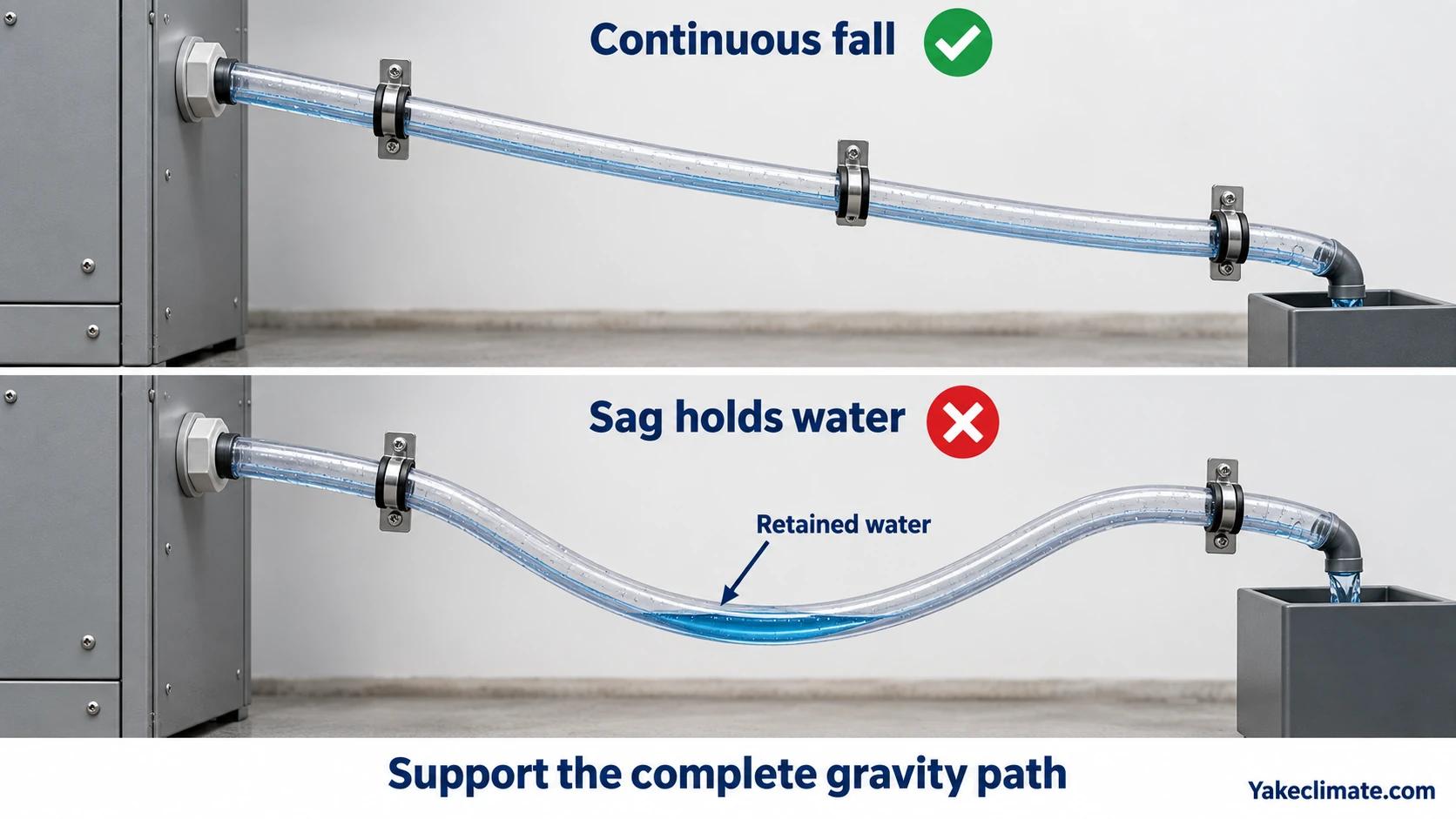
A gravity line should:
- fall continuously from the unit;
- avoid sags that hold water;
- use the diameter and material required by the equipment;
- be supported so that vibration or service cannot create a high point;
- terminate where water cannot damage equipment or access areas;
- prevent insects and debris from entering;
- remain inspectable;
- preserve the enclosure boundary at the penetration.
The installed unit must be level or oriented as specified so that water reaches the outlet. A small mounting error can make the tray spill before the drain receives water.
Traps, Pressure and Backflow
Pressure at the collection pan and at the drain outlet must be compared during fan operation, shutdown and any shared-line event. Enclosure pressure alone does not tell whether water will flow.
Possible problems include:
- a pan below outlet pressure drawing air inward through an unsealed drain and impeding gravity flow;
- a discharge point or shared line at higher pressure than the pan, reducing the head available for drainage;
- a trap drying out and becoming an uncontrolled air path;
- an external drain backing up into the equipment;
- wind-driven rain entering an exposed termination.
Do not add or remove a trap by habit. Identify pan pressure relative to the discharge point, follow the selected equipment’s approved drain and trap arrangement for that differential, and check operation through fan and pump cycles. Positive pan pressure can help drive water toward a lower-pressure outlet, but it does not replace the approved seal, safe termination or backflow review. If a water seal is required, define how it remains primed and how blockage is detected.
Pumped Drainage
A condensate pump may be required when:
- the unit is below the available discharge point;
- there is no continuous gravity fall;
- the drain has to cross an internal obstruction;
- the external termination must be higher.
Pump review should include:
- pump capacity at the actual lift;
- reservoir volume;
- duty cycle;
- power supply;
- high-level switch;
- pump-failure alarm;
- check valve where needed;
- overflow destination;
- access for cleaning and replacement;
- behaviour after power loss.
A pump adds a component that can fail. The BMS or EMS should not rely only on “dehumidifier running” if a blocked or failed pump can prevent water removal.
Protect the Enclosure Penetration
The drain penetration must be shown on the cabinet or container drawing.
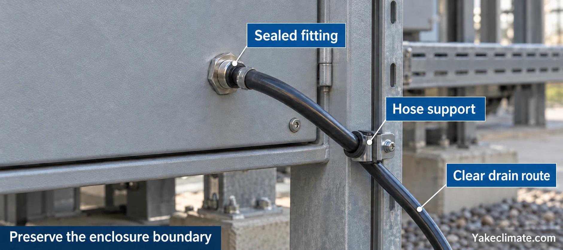
Confirm:
- approved gland, bulkhead or fitting;
- hole location and edge protection;
- sealing method;
- strain relief;
- external mechanical protection;
- compatibility with the enclosure's required protection;
- a drip path that does not run back along the hose;
- no interference with cables or service doors.
An improvised hole can become the largest water and air leakage path in the enclosure.
Freezing Conditions
Water in an external drain can freeze even when the enclosure is warm.
Assess:
- minimum outdoor temperature;
- exposed hose length;
- low points that retain water;
- insulation or heat tracing where permitted;
- whether the equipment can operate while the drain is frozen;
- alarm and shutdown response;
- thawing and inspection access.
The dehumidifier operating range alone does not prove that the drain system is suitable for winter.
Discharge Location
Condensate should not:
- drip onto foundations where it can freeze;
- wet cable trenches;
- run across a walkway;
- enter another electrical enclosure;
- collect beneath the container and increase local moisture;
- discharge where wind carries it back to vents or penetrations.
Follow site drainage and environmental requirements. If water quality or contamination is a concern, the project owner should define the permitted disposal route.
Shared Drain or Separate Drain
A shared drain can reduce penetrations, but it creates common-mode risks:
- one blockage affects several units;
- pressure from one system reaches another;
- it becomes difficult to identify which unit is producing water;
- maintenance on the line affects every connected device.
Separate drains are easier to diagnose but require more penetrations. The decision should follow system layout, maintenance and failure consequences.
Installation Checklist
- Confirm the unit's required orientation.
- Verify tray fall toward the outlet.
- Confirm hose/pipe diameter and material.
- Route a continuous fall or define the pump.
- Check pressure and trap requirements.
- Protect and seal the penetration.
- Define the external termination.
- Check freezing and backflow.
- Provide inspection and cleaning access.
- Define high-level, blockage or pump-failure response.
Commissioning the Drain
Do not wait for natural humidity to prove the drain.
Commissioning can include:
- introducing a controlled quantity of clean test water at the approved point;
- observing collection with the unit in installed orientation;
- verifying continuous flow to the termination;
- checking every joint for leakage;
- testing pump start, stop and high-level alarm;
- simulating blockage where the procedure permits;
- confirming remote alarms;
- recording the result and installed photographs.
Avoid test methods that wet live electrical equipment or bypass manufacturer instructions. Use the broader battery-enclosure commissioning checklist to record the drain test alongside control, alarm and enclosure checks.
Maintenance
Define an inspection interval based on dust, insects, freezing, water quality and site access.
Inspect:
- tray and channel contamination;
- hose kinks and supports;
- external termination;
- trap condition;
- pump reservoir and check valve;
- signs of backflow;
- penetration seals;
- alarm function.
Drainage that cannot be seen or tested is difficult to trust across a distributed BESS fleet.
Discussing a Drainage Integration
Yakeclimate designs and manufactures industrial dehumidification equipment for complex climate applications, with a focus on agriculture and energy projects.
We co-develop application-specific dehumidification equipment around the operating conditions, interfaces, and integration requirements of the wider project or system.
Review cabinet equipment, read how condensation-control units work, or contact Yakeclimate with the installation drawing and drain route.
FAQ
Frequently Asked Questions
Is gravity drainage always preferred?
It is simpler when a continuous fall to a safe termination is available. It is not suitable when the outlet must rise or when pressure and routing prevent reliable flow.
Does a condensate drain need a trap?
It depends on the selected equipment and the pressure difference between the collection pan and discharge point. A negative-pressure pan may draw air inward and impede drainage without an approved seal; positive-pressure arrangements can require a different trap design. Follow the manufacturer-approved configuration, keep any required seal primed, and test the installed path.
What happens if the external drain freezes?
Water can back up into the tray or enclosure. Assess winter conditions, retained water, insulation or heat tracing where permitted, and define alarm or shutdown behaviour.
Should the drain have an alarm?
Where blockage, pump failure or high water can wet electrical equipment, an alarm or interlock should be considered. The project should define the required failure response.
Can several dehumidifiers share one drain?
They can when capacity, pressure, backflow, maintenance and common-mode blockage are addressed. Separate drains can make faults easier to identify.
How should the drain be tested?
Test the installed orientation and complete path with a safe approved method, verify gravity or pump operation, inspect leaks and terminations, and record alarms and results.
