
1. What the Unit Does
Condensation is water that forms when a surface cools below the dew point of the air touching it. Dew point is the temperature at which air becomes saturated and water starts to condense.
A cabinet condensation-control unit removes water from internal air, discharges that water through a defined route, and uses a sensor or external command to decide when to operate. Its purpose is to lower the enclosure dew point or keep the relevant surfaces above it. It does not repair water ingress, provide fire protection, or replace the project's ventilation safety function.
Understanding the complete water path, from humid air to discharged condensate, is more useful than treating the unit as a black box.
2. The Control Loop
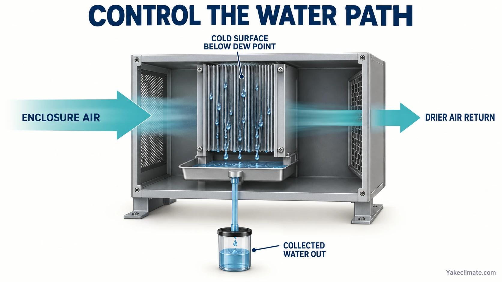
A practical cabinet unit performs five steps:
- It draws enclosure air across a cold surface.
- The cold surface falls below the air's dew point.
- Water vapour condenses into droplets.
- The droplets enter a collection and drainage path.
- The dried air returns to the enclosure.
A controller then uses temperature, humidity, dew point, run time, or an external signal to start and stop the process. Status and alarm signals may be made available to the wider monitoring system, depending on the selected configuration.
The unit itself intentionally creates condensation. Good equipment keeps that condensation inside a controlled internal path and removes it from the protected space.
3. Why Dew Point Matters
Relative humidity changes when air temperature changes, even if no water is added or removed. Dew point describes the actual moisture content more directly.
Example: air at 35 °C and 50 % RH has a dew point near 23 °C. If a cabinet wall, cable gland, or cold plate falls below 23 °C, water can form even though the RH value does not look extreme.
The unit therefore needs a target that relates to the coldest relevant surface. The engineering rule is:
Keep internal dew point below the coldest relevant surface temperature, with a margin that accounts for sensor error, spatial variation, and control response.
See Condensation Risk in Battery Enclosures for the calculation and measurement method.
4. Thermoelectric Units
A thermoelectric unit applies direct current to a semiconductor module. One side becomes cold and the other becomes warm. A fan moves enclosure air across the cold heat exchanger, where water condenses. The warm side rejects the transferred heat.
This route has several practical characteristics:
- compact dimensions for cabinet mounting;
- no refrigerant circuit or compressor;
- lower water-removal capacity than larger refrigerant equipment;
- performance that still varies with temperature and humidity;
- a need to keep both cold-side and hot-side airflow clear;
- continuous condensate drainage or collection.
The wide temperature range of a particular thermoelectric model can be useful in outdoor enclosures, but it must be read from that model's approved specification rather than assumed for the technology as a whole.
5. Refrigerant-Cycle Units
A refrigerant unit uses a compressor, evaporator, condenser, and expansion device. Enclosure air first passes over the cold evaporator. Water condenses and drains away. The air then passes over the condenser, where it is reheated before returning to the enclosure.
This route provides higher water-removal capacity and can suit larger enclosures or containerised systems. The main constraints:
- the permitted operating temperature range;
- declining water removal as temperature and moisture content fall;
- compressor start, current, and vibration requirements;
- airflow and heat rejection;
- refrigerant-system protection;
- access for filters, drains, and service.
| Comparison | Thermoelectric | Refrigerant |
|---|---|---|
| Water-removal capacity | Lower | Higher |
| Format | Compact, cabinet-mounted | Larger, suits containers |
| Refrigerant circuit | None | Compressor and charge |
| Cold operation | Model-specific | Limited by operating envelope |
| Typical use | Small enclosures | Larger cabinets, containers |
6. The Condensate Path
The water path should be visible in the design review:
Cold surface → collection tray or channel → drain connection → hose or pipe → safe dischargeProblems occur when any part is missing or poorly arranged. A tilted unit can direct droplets away from the intended channel. A level tray with an uphill hose can overflow. A hose exposed to freezing can block. An open penetration can defeat the cabinet boundary. A badly placed discharge can wet the same enclosure the unit is meant to protect.
The project should define the expected installation orientation, permissible drain route, hose material, minimum fall, external termination, and any alarm required for blockage or pump failure.
See Condensate Drainage in Sealed Battery Cabinets and Containers for a full review checklist.
7. Airflow Inside the Cabinet
The unit can only treat air that reaches it. Dense battery racks, cable ducts, and solid partitions create separate air zones. If the inlet and outlet face each other across a short open path, the unit may recirculate its own dry air while the roof and remote wall remain humid.
Review:
- inlet and outlet clearances;
- whether supply air can reach the coldest surfaces;
- obstructions created after cable installation;
- warm zones around power electronics;
- stagnant zones near the enclosure floor or roof;
- interaction with fans, cooling units, and required ventilation.
Airflow should be assessed after the cabinet is populated, not on an empty enclosure drawing.

8. Control Input and Interface Boundaries
For a simple RH switching requirement, verify the switching point, sensor location, hysteresis and actuator rating. For condensation risk, compare air dew point with the relevant cold-surface temperature; the controller may receive a dew-point signal or calculate it from temperature and RH. Either route still needs defined thresholds, fault handling and a commissioning test.
If BMS or EMS communication is required, specify the actual measurements, status and alarms, command owner and interface test. A shared protocol name alone does not prove that two devices expose compatible points.
Use Connecting Dehumidifiers to BMS/EMS for the interface review method. Bring the control objective, cabinet and relevant-surface conditions, required signals, and responsibility map to the project review. The examples identify device roles; actual model suitability and the final operating sequence require project-specific confirmation.
9. What a Condensation-Control Unit Does Not Do
It does not:
- stop rain or wash water entering through a damaged boundary;
- dilute flammable or hazardous gas;
- determine the required fire-protection strategy;
- guarantee that every cabinet surface is safe if airflow is blocked;
- provide a fixed capacity independent of temperature and humidity;
- remove the need for drainage, inspection, and alarm handling.
Those boundaries should appear in the equipment specification so that the unit is not credited with a function it cannot perform.
10. Installation and Commissioning
Before releasing the cabinet drawing, confirm:
- mounting orientation and fasteners;
- inlet and outlet clearance;
- service access;
- power supply and protection;
- drain routing and termination;
- sensor location;
- local and remote controls;
- heat released inside the enclosure;
- interaction with cooling and ventilation;
- environmental limits during normal operation and shutdown.
Commissioning should demonstrate the complete chain rather than only prove that the fan starts:
- verify sensor readings against a reference instrument;
- confirm start and stop behaviour at the intended thresholds;
- observe water entering the collection path;
- test the drain with the unit in its installed orientation;
- verify run, fault, and alarm indications;
- check BMS or EMS data and command direction where provided;
- confirm that airflow reaches remote zones;
- record temperature, RH, or dew point during a representative recovery test;
- define what result constitutes acceptance for the project.
11. Discussing a Cabinet Integration
Industrial Dehumidification for Complex Climate Applications
Yakeclimate designs and manufactures industrial dehumidification equipment for complex climate applications, with a focus on agriculture and energy projects.
We co-develop application-specific dehumidification equipment around the operating conditions, interfaces, and integration requirements of the wider project or system.
Review the energy-storage equipment family or contact Yakeclimate with the cabinet drawing, environmental range, drain route, and required signals.
FAQ
Frequently Asked Questions
What is the difference between a heater and a condensation-control unit?
A heater raises surface and air temperature but does not remove water. A condensing dehumidifier intentionally cools part of its heat exchanger below dew point, collects the water, and returns drier air. Some units add heat to the enclosure as a consequence of operation, but water removal remains the primary function.
How does a thermoelectric unit work?
Current through a semiconductor module creates a cold side and a warm side. Air passing over the cold side condenses water; the water is collected and drained. The warm side rejects heat. Capacity and operating limits remain model-specific.
How does a refrigerant-cycle unit work?
A compressor circulates refrigerant through an evaporator and condenser. Air is cooled below dew point at the evaporator so that water condenses, then reheated at the condenser before returning to the cabinet.
Where should the sensor be placed?
Place it where it represents the controlled risk, away from direct discharge and abnormal heat sources. If the cabinet has several thermal zones, one sensor may not represent the coldest surface. Temporary multi-point logging can identify the correct permanent location.
Can the unit report to a BMS?
It can when the selected configuration includes the required signal or communication interface. The project must confirm the exact functions, protocol details, register map, alarm definitions, and commissioning method rather than assume compatibility from a protocol name.
What must commissioning verify?
Sensor accuracy, start and stop logic, water collection, drainage, airflow, local and remote alarms, communication data where fitted, and recovery against an agreed environmental target.
References
- Modbus Organization: Introduction to Modbus — modbus.org
- Modbus over Serial Line Specification and Implementation Guide — PDF
