
A multi-cabinet battery energy storage system needs more than identical dehumidifiers. Consistency depends on using the same equipment definition, sensor basis, control states, alarm meanings, communication map, drainage arrangement, maintenance method and acceptance test.
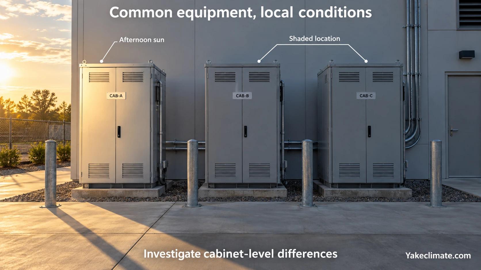
At the same time, every cabinet may not experience the same moisture load. Position, solar exposure, cable routes, door use, airflow and cooling operation can create local differences. The objective is a common engineering standard with traceable cabinet-level results.
Define What “The Same” Means
Start with a controlled equipment baseline:
- model and hardware revision;
- firmware or controller version;
- electrical supply;
- process-air arrangement;
- drain and condensate-alarm configuration;
- sensor type and mounting location;
- approved setpoint range;
- communication protocol and register map;
- alarm list;
- service parts and maintenance interval.
Record approved alternatives. A silent component substitution can change airflow, capacity, alarm behaviour or communication.
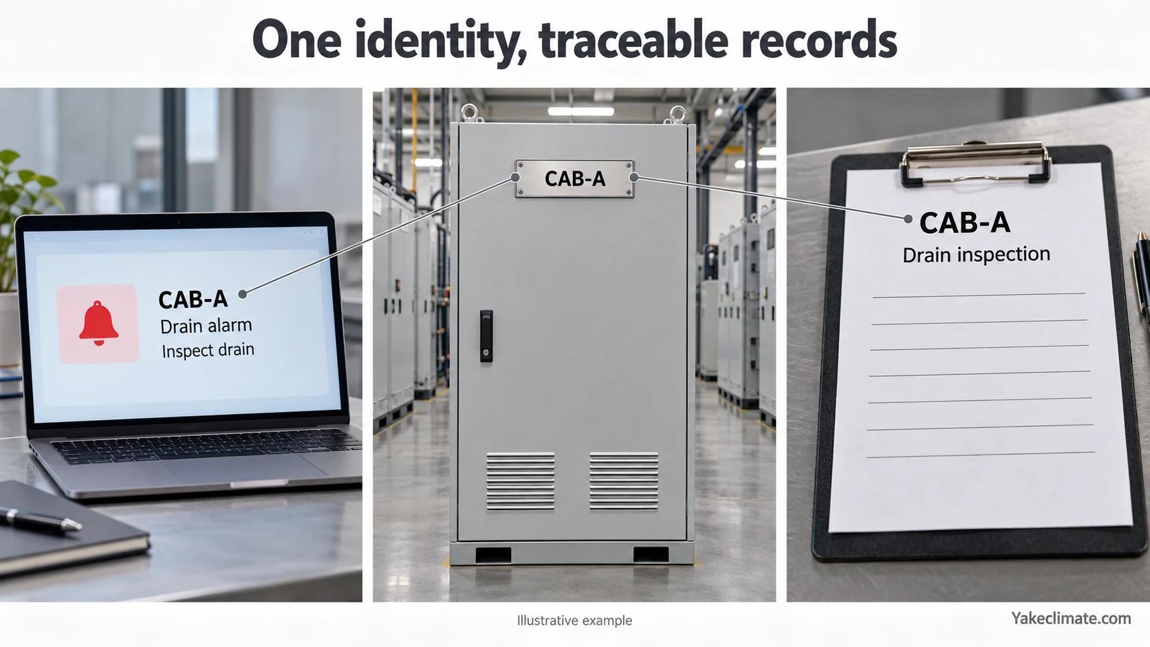
Give Every Cabinet a Unique Identity
Each cabinet and environmental-control device should have a stable identifier that appears in:
- drawings;
- controller address;
- BMS or EMS point names;
- commissioning sheets;
- alarm history;
- maintenance records;
- spare-parts records.
A technician should be able to move from an alarm in the monitoring system to the physical cabinet, device, sensor and drain without ambiguity.
Standardize Sensor Location Before Comparing Values
Two identical sensors in different thermal zones will report different conditions. Define:
- mounting height and compartment;
- distance from supply air, heat sources and walls;
- surface-temperature monitoring point where required;
- outdoor reference location;
- calibration and replacement method.
If a cabinet requires a different location because of its layout, document the exception. Do not compare fleet trends without understanding the measurement position.
Use a Common Control-State Model
Define the states that every unit can report. A practical model may include:
- available;
- running;
- standby;
- inhibited by external command;
- local/manual mode;
- fault;
- communication loss;
- maintenance.
The actual names and transitions depend on the controller. The important point is that the same state means the same thing across all cabinets.
Clarify which system has authority to:
- enable or disable the unit;
- change setpoints;
- acknowledge alarms;
- select local or remote mode;
- override operation during maintenance;
- command operation after restart.
Unclear ownership can create conflicting commands between the local controller and BMS or EMS.
BESS Dehumidifier Lead/Lag Control: Define the Sequence
Identify each device, its protected air volume, sensor basis and approved configuration. Confirm that the proposed group can serve the intended volume; proximity or matching models alone do not establish this. Record available, local/manual, inhibited, fault and maintenance states, and command authority.
Lead/lag labels do not define a complete sequence. Agree these decisions for the actual group:
| Decision | Required definition |
|---|---|
| Demand | Approved environmental input or request, responsible controller, and required duty count |
| Rotation | Eligible devices, lead selection, change event, command and run feedback |
| Substitution | Failure trigger, permitted replacement and confirmation |
| Recovery | Approved return state and authority |
These are project questions, not default settings or proof of moisture capacity.
Retain the approved control record
Attach cabinet/zone identities, point list, firmware/configuration, control ownership and device documentation. Record communication-loss, maintenance/local-mode and restart behavior. Under approved commissioning procedures, compare commands, observed states and cabinet conditions; retain results and approval. Resolve exceptions through configuration change control before rollout.
Verify each agreed event above, including normal duty, rotation, unavailable equipment and recovery. The approved sequence must specify expected states and evidence.
Separate Measurement, Command and Status
Do not use one field for several meanings. Keep distinct points for:
| Point type | Examples |
|---|---|
| Measurement | temperature, RH, dew point, surface temperature |
| Command | enable, reset, setpoint |
| Status | run, standby, local/remote, drain condition |
| Alarm | sensor fault, high moisture, fan fault, drain alarm |
| Configuration | address, limits, firmware, scaling |
For every point, define unit, scaling, valid range, update rate, read/write permission and failure value.
RS485 describes a physical communication layer. It does not by itself confirm Modbus, a register map or compatibility with a specific BMS/EMS. Confirm the protocol and fields for the selected model and project.
Make Alarm Meanings Actionable
An alarm list should state:
- trigger condition;
- persistence or delay;
- reset behaviour;
- severity;
- operator action;
- maintenance action;
- safe equipment response;
- message shown in the BMS or EMS.
Avoid one generic “dehumidifier fault” if the operator needs to distinguish sensor failure, drain blockage, fan failure and communication loss.
Also avoid alarm flooding. A site-level high-dew-point event may affect many cabinets at once. The monitoring design should help operators identify the common cause while preserving cabinet-level evidence.
Define Communication-Loss Behaviour
When communication fails, decide whether the local controller:
- continues its last valid automatic control;
- uses a local fallback setpoint;
- stops;
- raises a local and remote alarm;
- stores data for later retrieval.
The correct choice depends on system safety and operating requirements. It must be tested rather than assumed.
Keep Drainage Configurations Traceable Across Cabinets
For every condensate-producing unit, use an approved drain configuration tied to the cabinet ID. Record route or trap exceptions, blockage/high-water alarm, inspection point and safe discharge; do not assume one hose arrangement fits every pressure or freeze condition. Keep full routing, pressure, backflow and test procedure in Condensate Drainage in Sealed Battery Cabinets and Containers.
A perfectly controlled dehumidifier can still create a site problem if one cabinet has a kinked hose or an uphill drain.
Use One Baseline Commissioning Record
Use the same evidence fields for every cabinet: identity and configuration, sensor plausibility, command and state, communications, alarms, drain and airflow, and recovery after the agreed event. Record actual values and approved exceptions against each cabinet ID. Use the full test method in the BESS Humidity-Control Commissioning and Validation Checklist.
Record actual values, not only pass/fail. The data reveals outliers that a checklist alone may hide.
Analyse the Fleet Without Hiding Local Differences
Useful comparisons include:
- time above the agreed dew point;
- minimum surface-to-dew-point margin;
- run hours;
- condensate or drain events;
- fault count;
- recovery time after door opening;
- sensor drift;
- energy use where measured.
Investigate outliers before changing all cabinets. One cabinet may face afternoon sun, a damaged gasket, a cable-trench connection or a blocked air path.
Maintenance Consistency
Create one service procedure covering:
- safe access and isolation;
- filter inspection or replacement;
- sensor verification;
- drain cleaning;
- fan and airflow check;
- gasket and penetration inspection;
- alarm test;
- firmware or configuration control;
- return-to-service check.
Use cabinet-specific records so repeat faults and environmental differences remain visible.
Configuration Change Control
Restrict setpoint and firmware changes to authorised roles. For each change, record:
- cabinet ID;
- previous and new value;
- reason;
- date and person;
- approval;
- validation result.
If a fleet-wide change is needed, test it on a controlled subset where practical and confirm that it does not conflict with equipment limits or safety functions.
Information Needed for a Multi-Cabinet Project
Provide:
- cabinet quantity, arrangement and zones;
- equipment model and acceptable alternatives;
- environmental targets and cold surfaces;
- sensor and communication architecture;
- BMS/EMS point list;
- control ownership and failure state;
- drainage standard;
- commissioning test;
- spares and maintenance strategy;
- data-retention and reporting requirements.
Discussing Multi-Cabinet Integration
Yakeclimate designs and manufactures industrial dehumidification equipment for complex climate applications, with a focus on agriculture and energy projects.
We co-develop application-specific dehumidification equipment around the operating conditions, interfaces, and integration requirements of the wider project or system.
Explore energy-storage dehumidifiers, review condensation control units or contact Yakeclimate with cabinet quantity, point list and acceptance requirements.
FAQ
Frequently Asked Questions
Should every cabinet use the same humidity setpoint?
Only when the equipment limits, cold-surface conditions and project requirements support it. Use a controlled baseline, then document justified exceptions.
Can one sensor control several cabinets?
It may not represent cabinets with different airflow, exposure or leakage. Validate the zones before deciding which volume one sensor can represent.
Is RS485 enough to connect to the EMS?
No. Confirm the protocol, register map, scaling, addressing, permissions and failure behaviour for the selected equipment.
Which alarms should be standard?
At minimum, define the alarms required to identify loss of environmental protection and equipment failure. The exact list follows the device functions and project risk review.
How can inconsistent cabinets be found?
Compare actual measurements, run hours, recovery time, alarms and maintenance history using consistent sensor locations and time bases.
Should configuration changes be applied to every cabinet at once?
Use formal change control. Validate the change and its equipment limits before fleet-wide rollout, and keep a record for every affected cabinet.
