
An industrial dehumidifier should be sized from the moisture that must be removed at the actual entering-air condition—not from floor area alone. The minimum project brief needs the control objective, temperature and humidity design points, moisture sources, outdoor-air and leakage rates, peak operating schedule, recovery time, airflow path, drainage, power and service constraints. A final selection then checks equipment performance at those conditions and applies the required operating margin or redundancy.
This article shows how to prepare that brief. It is an educational sizing method, not an automatic model selector: projects with safety-critical equipment, low dew-point targets, uncontrolled infiltration, changing production loads or incomplete data need an application review.
The sizing sequence in one view
| Step | Question | Output needed before selection |
|---|---|---|
| 1 | What must be controlled? | RH, dew point, material moisture or recovery-time objective |
| 2 | Under what conditions? | Normal, peak and recovery temperature/humidity cases |
| 3 | Where does water enter? | Moisture-source register in kg/h or L/day |
| 4 | How does air move? | Ventilation, leakage, door opening and recirculation data |
| 5 | What must the unit deliver? | Required removal at the design entering-air condition |
| 6 | How will it be installed? | Air path, drainage, power, controls, access and redundancy |
| 7 | How will it be accepted? | Measured trend, condensate and pass/fail criteria |
Skipping the first four steps and beginning with a catalogue capacity is a common source of sizing error: an apparently large unit can still underperform when the load and entering-air condition are not defined.
1. Define the control objective
“Reduce humidity” is not a complete requirement. Select the variable that represents the actual risk.
Relative humidity is useful when a process, material or room specification is written as RH at a stated temperature. RH changes when temperature changes even if the amount of water vapour remains the same, so an RH target without its temperature is incomplete.
Dew point is usually the clearer variable when condensation is the risk. Condensation becomes possible when a surface reaches or falls below the surrounding air’s dew point. NIST defines dew point through the temperature at which condensation begins under constant pressure and water content; the practical project requirement is therefore a surface-temperature margin above dew point, not only a room RH value.
Material moisture content is appropriate for drying grain, seed, timber, coatings, concrete or other products. The air condition supports moisture transfer, but the material endpoint is the acceptance variable.
Recovery time matters after washdown, door opening, wet product entry, shutdown or a weather event. A unit that can maintain the steady condition may still be too small to restore the target within the allowed time.
Record the target, allowed excursion and measurement location. A single sensor near the dry-air outlet is not evidence that the coldest surface or least-mixed zone is protected.
2. Establish three design cases
Industrial projects rarely have one condition. Use at least these three cases:
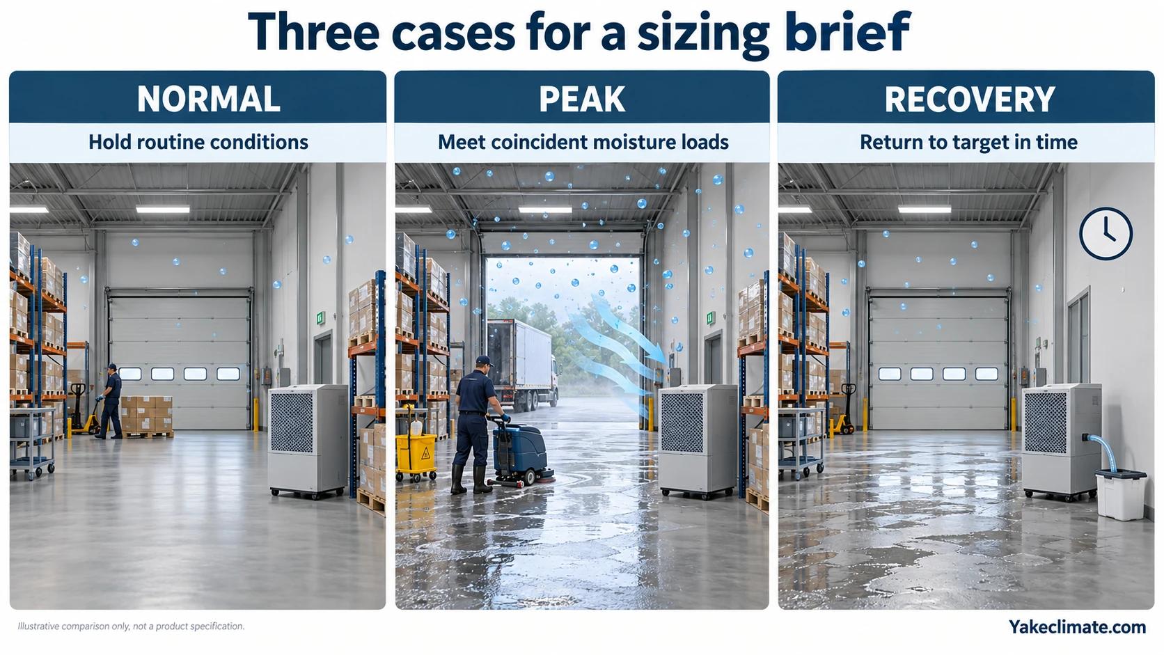
| Design case | Purpose | Typical inputs |
|---|---|---|
| Normal/steady | Hold the target during routine operation | Normal production, occupancy, doors and outdoor air |
| Peak | Survive the most demanding coincident load | Wet process, high outdoor humidity, full occupancy or frequent openings |
| Recovery | Return to target within a stated period | Initial water inventory and allowed pull-down time |
State the entering-air dry-bulb temperature and RH or humidity ratio for each case. ASHRAE’s mechanical dehumidification guidance treats entering condition as fundamental because refrigerant and desiccant equipment respond differently as temperature and moisture level change.
Do not choose the most humid condition automatically. For a refrigerant unit, the critical capacity point can be a cooler condition near the target, where less water is available to condense on the coil. For a condensation-risk project, the critical event may be a rapid surface-temperature drop while moisture content changes slowly.
3. Build a moisture-source register
The steady moisture load is the sum of water added by processes, people, products, ventilation and infiltration, minus any moisture removed by exhaust or other equipment. Put every source on the same time basis, normally kilograms per hour. Near ordinary indoor conditions, one kilogram of liquid water is approximately one litre, so daily condensate volume can also be a useful operational cross-check.
| Moisture source | Preferred evidence | Common mistake |
|---|---|---|
| Outdoor ventilation | Measured airflow plus outdoor and indoor humidity ratio | Comparing RH instead of humidity ratio |
| Envelope leakage | Pressure test, verified air-change estimate or operating trend | Assuming a nominal room volume makes leakage known |
| Doors and hatches | Opening area, frequency, duration and pressure difference | Counting openings but ignoring duration and wind/pressure |
| Occupants | Occupancy and published latent-load data for the activity | Using office data for physical work |
| Wet process or washdown | Water balance, mass loss or measured condensate | Treating an intermittent peak as a daily average |
| Wet product/material | Initial and final mass/moisture records over time | Using floor area as a proxy for water inventory |
| Combustion or steam | Fuel/process records and mass balance | Omitting temporary or cleaning operations |
| Existing HVAC removal | Coil/condensate data at the design condition | Assuming nameplate cooling equals latent capacity |
For an outdoor-air stream, calculate net moisture transport from dry-air mass flow and the humidity-ratio difference between the entering and leaving states: ṁ_water = ṁ_dry_air × (ω_in − ω_out). With dry-air flow in kg dry air/h and humidity ratio in kg water/kg dry air, the result is kg water/h. Use the sign consistently: wetter entering air adds load; drier entering air removes moisture. This airflow term covers air exchange only. Water released from product or material inventory is a separate source and must not be counted again in the airflow term.
Moisture load from air = dry-air mass flow × (outdoor humidity ratio − indoor humidity ratio)Use consistent units and keep the airflow ledger separate from the process or product ledger. If the outdoor humidity ratio is lower than the indoor target, that airflow removes rather than adds moisture; if it is higher, more ventilation increases the dehumidification load.
This is why “outside RH is lower” is not enough. Cold outdoor air can show high RH but still contain little water, while warm outdoor air can show a lower RH but carry more moisture. Convert both states to humidity ratio or dew point using a validated psychrometric method such as the Yakeclimate dew point calculator, whose calculation basis is documented from NIST references.
4. Separate steady load from stored water
Steady-state sizing answers how much water enters per hour after the space is near target. Recovery sizing also includes water stored in products, building materials, standing water and initially humid air, but that stored inventory must remain a separate recovery term rather than being added again to the air-exchange calculation.
For a simple measured recovery test:
- Define the start and end conditions.
- Measure condensate over the recovery window.
- Record ventilation, doors, process state and temperature during the test.
- Add any water removed by exhaust or drained elsewhere.
- Repeat under a representative demanding condition.
Condensate is useful evidence only when its collection boundary is known. A low condensate total can mean low moisture load, but it can also mean the unit is operating outside its effective condition, the drain measurement is incomplete, or water is leaving through ventilation.
For more detail on measured water removal and rating interpretation, see how much water a dehumidifier can collect in a day and how evaporation becomes a dehumidification load.
5. Compare capacity at the same condition
A daily removal figure is not independent of test conditions. Temperature and RH must travel with the capacity value.
When comparing alternatives, request the following on one table:
- technology and model;
- capacity at the project’s entering-air condition;
- airflow and available external pressure where ducted;
- operating temperature range and defrost behaviour;
- power at the comparison condition;
- control tolerance and sensor location;
- drainage method and failure/alarm handling;
- sound, heat rejection and maintenance access;
- quantity, duty/standby arrangement and failure consequence.
If only a favourable standard rating is available, treat it as a catalogue reference—not verified project capacity.
6. Check air distribution before adding capacity
Moisture removal occurs only from air that reaches the unit. Total capacity can appear adequate while cold corners, densely loaded racks, crop canopies, cable trenches or closed cabinets remain poorly mixed.
Map the air path from return to dry-air discharge. Check obstructions, short-circuiting, door state, pressure relationships and whether the return sample represents the risk zone. In large or divided spaces, multiple smaller units can provide better distribution and resilience than one unit with the same total rating.
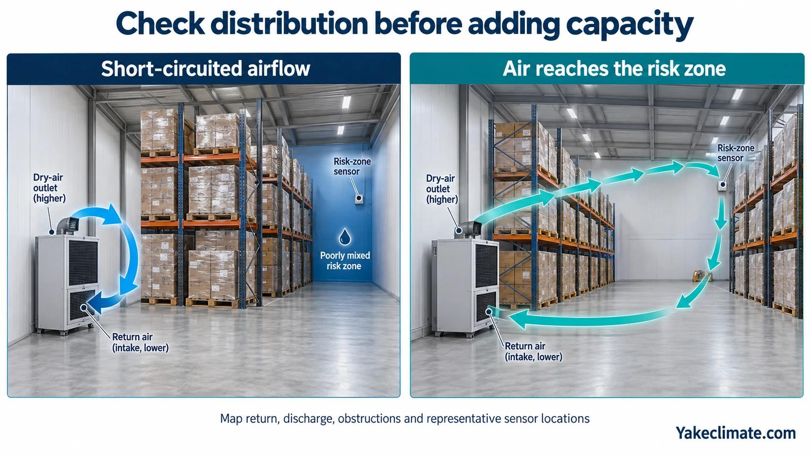
For ducted systems, include pressure loss at dirty-filter condition. For local enclosures, confirm that internal circulation reaches the cold surfaces; do not assume room control protects a sealed or weakly ventilated cabinet.
7. Add installation and lifecycle constraints
The project brief is not complete until it covers:
- available electrical supply and allowable starting demand;
- continuous drainage route, trap, fall, freezing risk and high-level alarm;
- condensate destination and any contamination restrictions;
- installation orientation and structural support;
- service clearances and filter access;
- heat added to the room and coordination with cooling/heating;
- BMS, EMS or local control signals actually required;
- duty/standby philosophy and acceptable downtime;
- corrosion, dust, washdown, outdoor exposure or enclosure requirements;
- commissioning instruments and trend interval.
These inputs decide product format and integration. They also prevent a correctly sized refrigeration circuit from becoming an unserviceable installation.
8. Use margin deliberately
An unexplained percentage is not a substitute for missing data. First identify uncertainty: infiltration, future production, filter loading, seasonal condition, recovery time, distribution or equipment degradation. Then decide whether the response is measurement, operating margin, staged capacity or redundancy.
A duty/standby requirement can double installed count without doubling the simultaneous design load. A future expansion allowance should be stated separately from the current load. Staging can improve part-load control, while a single oversized unit may cycle and provide uneven control.
9. Define acceptance before ordering
A defensible acceptance plan measures the controlled variable at representative risk locations under a defined operating case. Record temperature, RH and, where relevant, surface temperature or dew point. Record equipment state, doors, outdoor condition and production load so that a pass or failure has context.
Useful checks include:
- stable control over the agreed observation window;
- no unintended condensation at identified critical surfaces;
- condensate and trend behaviour consistent with the load estimate;
- alarms, drains, restart and communication functions tested;
- acceptable distribution between representative points;
- recovery achieved within the agreed time;
- baseline retained for later filter, leakage or process changes.
Project input checklist
Before requesting a model recommendation, prepare:
- Application and failure consequence.
- Space or enclosure dimensions and usable volume.
- Normal, peak and recovery temperature/humidity conditions.
- RH, dew point or material-moisture target and tolerance.
- Coldest surface and minimum expected surface temperature.
- Ventilation airflow and outdoor design moisture condition.
- Leakage, doors and pressure relationship.
- Process, product, people and cleaning moisture sources.
- Allowed recovery time and operating schedule.
- Air distribution, ducts and available static pressure.
- Power, drainage, controls and alarms.
- Installation, access, environment and redundancy constraints.
The same fields can be copied into a project-input worksheet before an inquiry is handed to engineering. Keeping the worksheet application-specific helps the engineering team check assumptions without relying on a generic capacity label.
When an engineering review is required
Escalate beyond an educational estimate when the target is a low dew point, when condensation has safety or reliability consequences, when operating temperature is near a technology limit, when infiltration is unknown, when multiple moisture sources overlap, when stored water drives recovery, or when the unit must interface with another control system.
Yakeclimate designs and manufactures industrial dehumidification equipment for complex climate applications. The next step is to submit the project inputs above so equipment performance and installation constraints can be checked against the wider project—not to select from floor area alone.
FAQ
Frequently Asked Questions
Can an industrial dehumidifier be sized by room area?
Area can help describe a space, but it does not quantify water entering through outdoor air, leakage, products, people or processes. Use a moisture-load and operating-condition brief for final selection.
Is the catalogue litres-per-day value the project capacity?
Only when the project entering-air condition matches the rating condition and the installation allows the published performance. Otherwise request performance at the actual temperature and humidity.
Should I size from peak load or average load?
Size for the demanding condition that the project is required to hold. Keep normal, peak and recovery cases separate so the chosen capacity, staging and redundancy can be explained.
Why can a large unit still leave condensation in one area?
The surface may be below dew point, or the air in that zone may not reach the unit. Check surface temperature, sensor location and air distribution before assuming that total capacity alone is inadequate.
What information should I send before asking for a model?
Send the control target, normal/peak/recovery conditions, moisture sources, airflows, leakage and openings, coldest surface, installation layout, power, drainage, controls and allowed recovery time.
Sources
- ASHRAE Handbook, Chapter 22: Humidifiers — air mass flow, humidity ratio and moisture-load calculation framework.
- ASHRAE Handbook, Chapter 25: Mechanical Dehumidifiers — dehumidification technology and operating-condition context.
- NIST: Algorithms for Psychrometric Calculations — traceable psychrometric calculation basis.
- NIST: An assessment of formulas for calculating dew-point temperature — dew-point definition and calculation assessment.


