
Select a ducted arrangement by coordinating moisture removal, airflow, available external pressure and the building’s controls. The dehumidifier may treat all or part of the circulated air; neither matching nor reducing the air-handler flow is a universal rule.
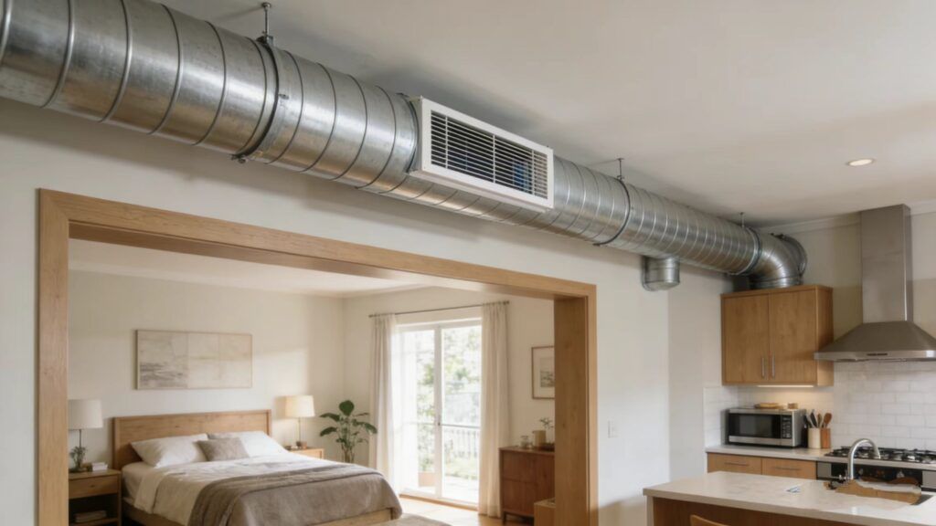
Cooling and dehumidification duties can require different airflows, but they are connected through the air states and the selected equipment. Check moisture removal, distribution and the permissible operating airflow together.
Three Arrangements
Standalone ducted. The unit has its own supply and return and can be arranged to operate outside HVAC cooling hours. It still interacts with room heat, ventilation and pressure; independent ductwork does not remove every coordination task. For the differing temperature and humidity duties, see temperature and humidity control in HVAC.
Integrated with the air handler, in parallel. The dehumidifier treats a selected part of the return air. The connection points and discharge route must follow the approved equipment arrangement. Determine the treated fraction from the load and attainable air states, then check fan interaction and controls; this layout has no automatic energy advantage.
Dedicated outdoor air treatment. Treating ventilation air before it enters the space can address that source’s moisture contribution. Calculate it from the ventilation rate and air states, while separately accounting for internal sources and infiltration. The remaining space duty and cooling requirement still need assessment.
Which arrangement suits a project depends on where the moisture comes from. Quantifying the sources, and confirming whether ventilation air dominates, is step one and is set out in commercial dehumidifier selection.
Link the Moisture Load to Airflow
Resolve these connected requirements:
How much water must be removed over the design interval? Establish the moisture balance and required operating conditions, including sources, air exchange and any relevant storage changes. Use a consistent rate such as kg/h.
How much air must cross the unit? For a steady air path without leakage or mixing across the measurement boundary, water removal is dry-air mass flow multiplied by the inlet-to-outlet humidity-ratio reduction. Volume flow needs the corresponding air density conversion; temperature and RH readings alone do not give a removal rate.
How must that air reach the zones? Distribution, mixing and terminal requirements must be satisfied within the unit’s permitted airflow range. Reconcile these with the moisture-removal calculation instead of sizing only for distribution or copying the cooling airflow.
For parallel treatment, solve the mixing and space moisture balance using the proposed leaving-air condition and treated flow. There is no universal quarter-to-third fraction. Check the result against actual equipment performance and include all operating fans before comparing energy.
| Arrangement | Best fit | Main risk to control |
|---|---|---|
| Standalone ducted | A defined room or process needs humidity control independent of HVAC runtime. | Poor mixing if the supply and return are placed for convenience rather than air pattern. |
| Parallel with air handler | The building already has useful circulation and the latent load is not only outdoor air. | Check pressure interaction, fan operation and coordinated controls. |
| Dedicated outdoor air treatment | Ventilation air is the dominant moisture source. | Underestimating outdoor design humidity or changing ventilation rate after selection. |
The External Static Pressure Budget
External static pressure is the pressure allowance outside the unit’s stated rating boundary at a specified airflow. Use the fan or unit performance data for the installed configuration; a pressure number alone does not establish deliverable airflow or duct reach.
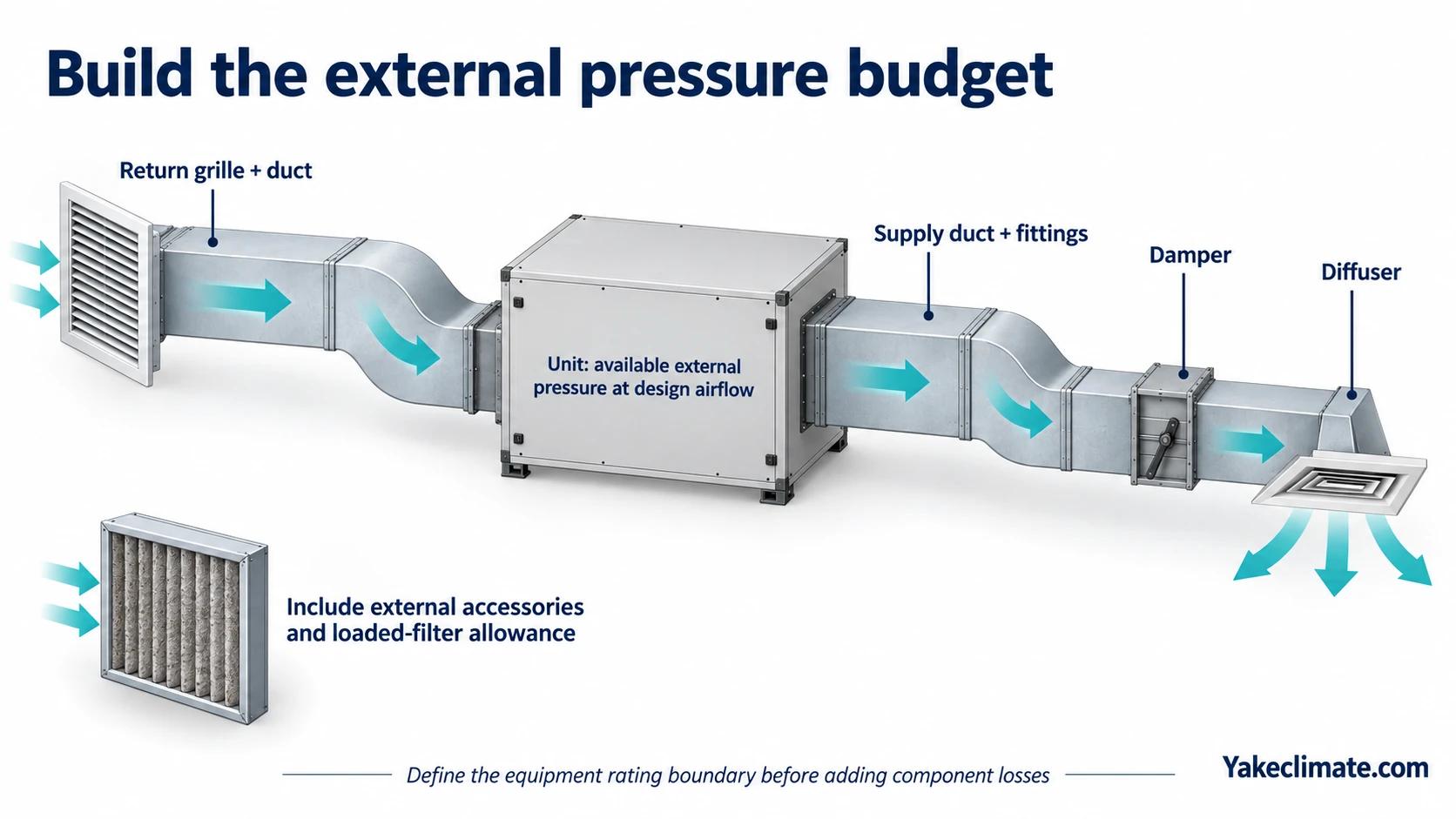
Build the budget explicitly:
- Supply duct: straight lengths, fittings, transitions, dampers.
- Diffusers or grilles at design airflow.
- Return duct and grille.
- External filtration, with the agreed loaded-filter allowance. Identify which filter losses are already included in the unit rating.
- Any external coil, attenuator or accessory on the relevant path.
- A margin for installation variation.
Add losses along the relevant supply-and-return path at design flow; do not sum unrelated parallel branches as though they were in series. Compare with available external pressure at that flow and check other operating modes.
Duct reach depends on the pressure budget, not a unit size or duct-length label. Check the selected model and configuration before fixing the layout. For flexible duct, use pressure-loss data that represent the actual size, extension and bends rather than assuming a fully stretched installation.
If resistance exceeds the selected fan’s capability, the intended airflow may not be achieved. Constant-airflow control also has operating limits. Measure the installed operating point and reassess distribution and removal; do not assume every fan responds identically or add capacity before diagnosing the cause.
Coordinating With Existing HVAC
Where the dehumidifier shares air paths with the building system, several interactions have to be resolved explicitly.
Control priority. Independent controllers may conflict or cycle unnecessarily, but oscillation is not inevitable. Agree sensor locations, setpoints, deadbands, enable signals and demand priorities, then test simultaneous cooling and dehumidification calls.
Heat rejection. When condenser heat is returned to the process air, account for the warmer discharge in the building heat balance. Other configurations reject heat elsewhere. Confirm the selected circuit and any useful reheat before claiming an energy benefit.
Airflow interaction. A dehumidifier discharging into a duct that also carries air handler flow affects the pressure regime for both. Where the air handler is variable-volume, that interaction changes with load.
Fan interlocks. Establish the required circulation path in occupied and unoccupied modes, including whether the dehumidifier is permitted to operate with the air-handler fan off.
Filtration. Where the dehumidifier draws from a duct, the filtration upstream of it affects its coil fouling rate and therefore its capacity over time.
Resolve these interfaces during design and verify them at commissioning, including changes in air-handler flow.
The Zoning Limitation
A shared unit may use a single sensor, return-air sensing or a multi-zone control arrangement. One measured location cannot establish that every room meets its target; compare all served zones with their requirements.
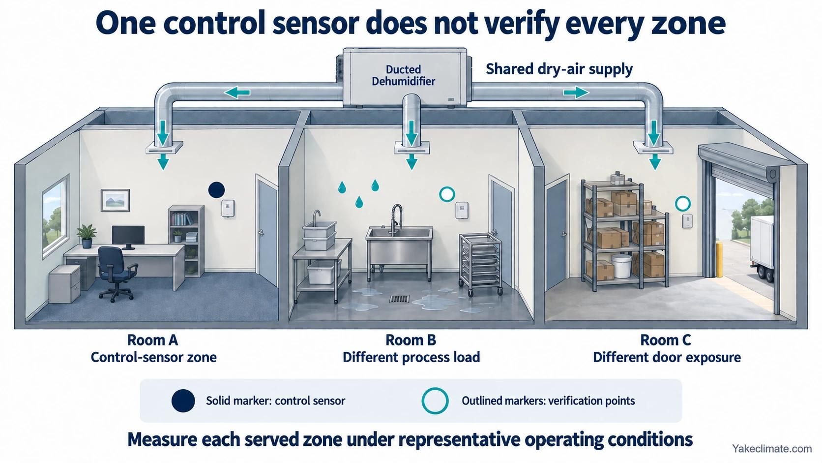
Different moisture loads, airflow balances and operating schedules can produce different zone conditions. Assess the likely variation and verify it under relevant conditions rather than assuming either uniformity or inevitable divergence.
The options:
Accept it, where the divergence is within tolerance. This requires actually estimating the divergence rather than assuming it is small.
Zone the distribution where the equipment and controls support it. Check minimum unit airflow and pressure across the planned damper positions, not only when every branch is open.
Use separate units where independent control is justified. Additional units do not automatically provide backup for another zone; redundancy requires suitable capacity and air paths.
Use a critical-zone sensor where that is the agreed control basis. Verify the other rooms against their own tolerances rather than assuming over- or under-treatment is acceptable.
The failure mode to avoid is a single unit serving zones with materially different loads, with the sensor placed wherever the controls contractor found convenient.
Drainage, Access and Noise
Drainage. Select gravity drainage or a compatible pump for the installation. For a negative-pressure pan, use the manufacturer’s trap detail based on the applicable pan suction and required margin; a single “depth greater than pressure” rule does not define the full geometry. Provide priming and service access and verify drainage in the required fan modes. See commercial ceiling dehumidifiers.
Access. Filters, coil faces, drain pan and controls all need to be reachable. In a plant room this is straightforward; in a ceiling void competing with other services it needs to be secured at layout stage.
Noise. Assess both cabinet-radiated and duct-borne sound at the occupied spaces. Include any necessary attenuation in the layout and pressure budget.
Commissioning and Verification
Ducted systems have more places for the design intent to be lost, so verification matters more.
- Measure airflow as installed, at the unit and at the terminals. Design airflow and installed airflow frequently differ.
- Measure external static pressure at the agreed points and compare it with the design budget and measured airflow. Investigate discrepancies alongside load, control and equipment condition.
- Record entering and leaving temperature and humidity together with measured airflow and the measurement boundary. Use consistent air properties and a suitable stable test period to estimate moisture removal, accounting for operating cycles where relevant.
- Verify conditions in every zone served, not only the sensor zone. This is where the zoning limitation shows itself.
- Test the control sequence, including the interaction with the HVAC system and the unoccupied-period behaviour.
- Record the as-installed configuration: duct layout, damper positions, sensor locations, control settings.
The commissioning baseline is what allows a later capacity complaint to be assessed, as described in how long should a dehumidifier run.
Information to Prepare
- Building use, zones served, and the humidity requirement in each, including whether they differ.
- Moisture load by source, with ventilation and infiltration identified separately.
- Target condition and tolerance, and whether it must be held during unoccupied periods.
- Existing HVAC: type, capacity, airflow, whether variable-volume, and its control system.
- Intended arrangement: standalone, parallel with the air handler, or outdoor-air treatment.
- Proposed duct layout with lengths, fittings and terminals, for the pressure budget.
- Available plant space or ceiling void, with access provision.
- Drain point location and level.
- Power supply available at the intended location.
- Noise requirement for the served spaces.
- Control system, available interfaces and intended sensor locations.
Discussing a Project
Yakeclimate designs and manufactures industrial dehumidification equipment for complex climate applications, with a focus on agriculture and energy projects.
We co-develop application-specific dehumidification equipment around the operating conditions, interfaces, and integration requirements of the wider project or system.
Duct design, HVAC integration and building services engineering remain with the project's mechanical engineers. Our scope is the equipment and its interface requirements: capacity at the design condition, airflow, external static pressure, drain connection, power and control.
Explore industrial dehumidifiers, review industrial ceiling dehumidifiers, or contact Yakeclimate to review the operating conditions for your project.
FAQ
Frequently Asked Questions
Should the dehumidifier handle the same airflow as the air conditioning?
It may, but it need not. Select airflow for required moisture removal at the achievable air states, distribution and the unit’s operating limits. For parallel treatment, calculate the treated fraction and mixing balance; do not assume a fixed ratio or an energy saving.
Can one ducted unit serve several rooms?
Yes, if the distribution and control plan meet the requirements of the served zones. Confirm the sensor arrangement, assess differing loads and verify each zone. Where dampers are used, maintain permitted unit airflow and pressure across their operating positions.
Should the dehumidifier be integrated with the air handler or standalone?
Choose from the moisture sources, required operating hours, available air paths and controls. Standalone ductwork, parallel integration and outdoor-air treatment each need a project-specific assessment; none is inherently the most efficient.
Why is my ducted dehumidifier underperforming?
Compare measured airflow and external pressure with the design basis, then check entering conditions, controls, drainage and loads. Fan response depends on its control and operating limits. Verify zone conditions before assuming the unit needs more capacity.
What drainage arrangement does a ducted unit need?
Use the specified gravity or pump arrangement. For a negative-pressure pan, follow the manufacturer’s trap geometry using the applicable pan suction and required margin. Provide priming and cleaning access, and test drainage in the required fan modes; do not size the trap from one generic depth rule.
How should a ducted system be commissioned?
Measure unit and terminal airflow, external pressure, and entering and leaving air conditions on a defined basis. Verify every served zone, drainage and the control sequence across required HVAC and unoccupied modes. Record layout, settings, sensors and any outstanding verification.
References
- ASHRAE Handbook - HVAC Systems and Equipment
- ANSI/ASHRAE Standard 62.1, Ventilation and Acceptable Indoor Air Quality


