
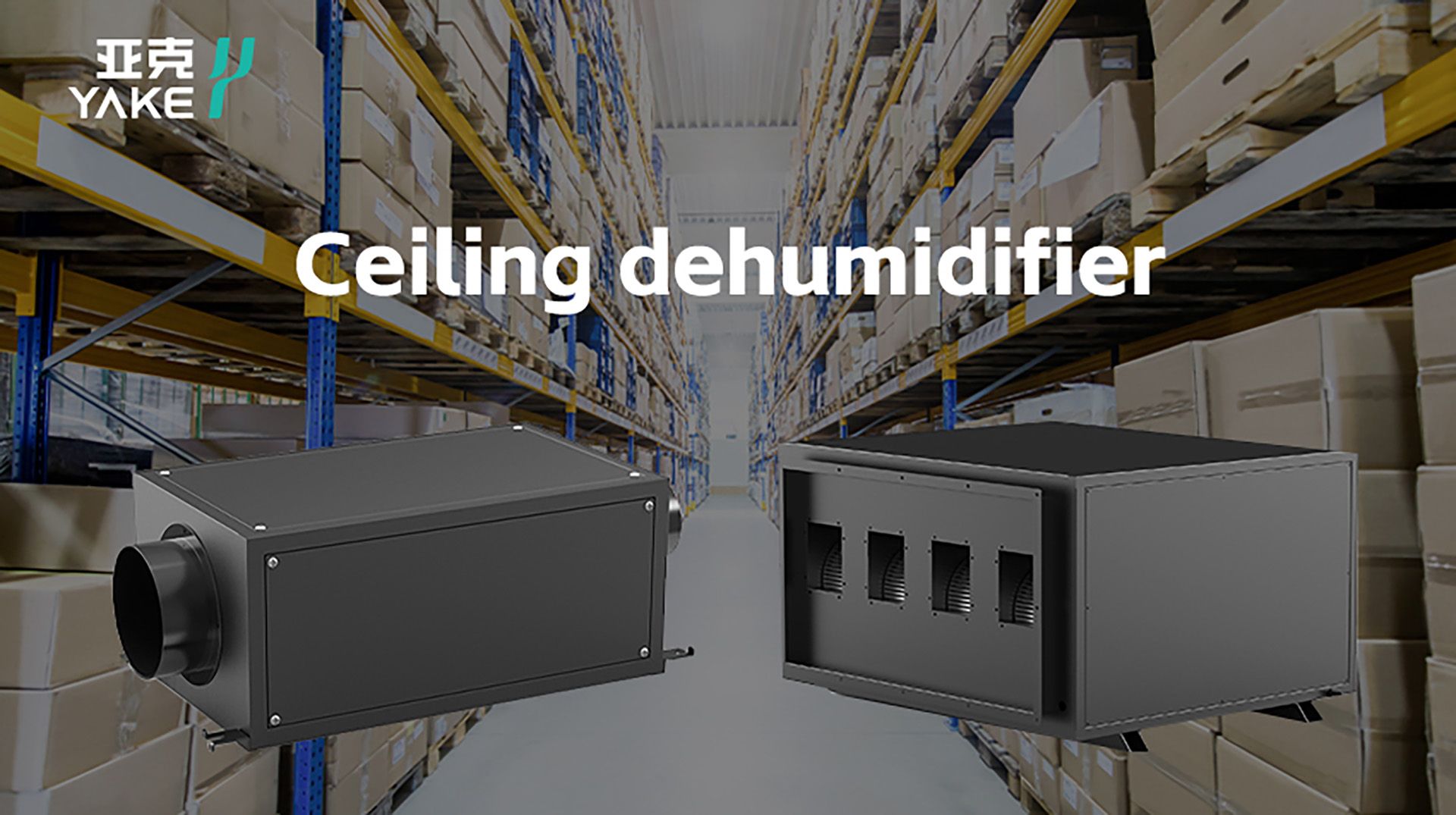
Ceiling-mounted dehumidifiers can free floor space for crops, storage or cleaning. Before choosing one, check whether the building can support it and whether air, condensate and maintenance personnel can reach the places they need to. The installation must serve the working zone, not simply fit inside the ceiling void.
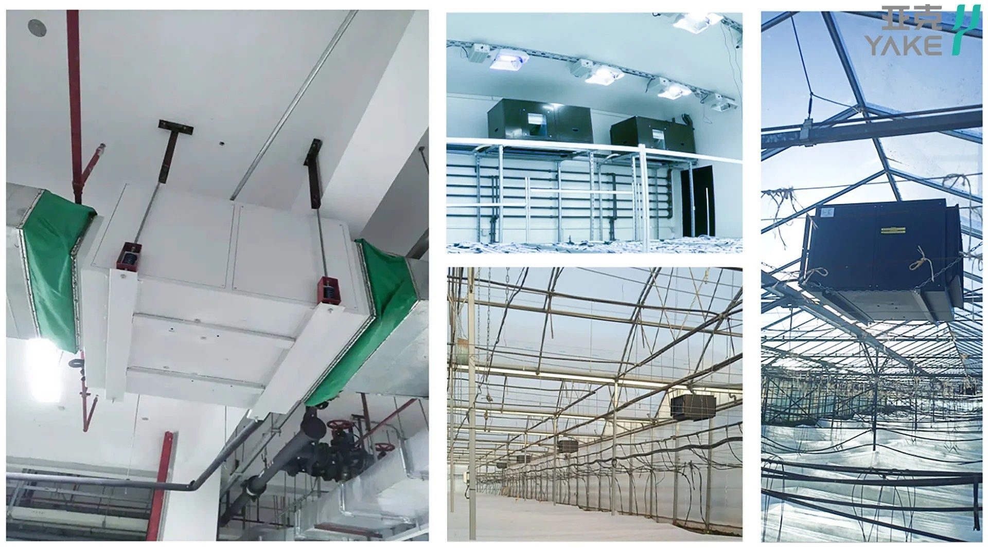

Structure, airflow, drainage and access need coordinated design at any mounting height. Overhead installation adds lifting, clearance and leak-consequence questions that should be resolved before equipment is ordered.
The Weight Is Real
A ceiling unit is a suspended mechanical load, not a light fitting.
Use the selected model’s current dimensioned drawing and operating weight for coordination. Catalogue capacity alone does not establish the suspended load, fixing arrangement or service clearance.
Four structural points follow:
Define the supported loads. Ask the structural engineer to account for the equipment, retained water, any attached services and applicable installation, vibration and maintenance loads. Provide separate safe access; do not assume the casing can support a person.
Verify the load path and fixings. Purlins can be structural members, but their suitability for an additional suspended load must be checked. Do not assume a suspended ceiling grid or an unverified fixing point is adequate. Have the project structural engineer approve the proposed support arrangement.
Specify vibration isolation with the support design. Compressor and fan vibration can travel through hangers, connections and the building structure. Select compatible mounts and flexible connections without compromising stability or the required load path.
Check the fixing environment. In greenhouses, food processing and other humid or washdown environments, the fixings themselves face a corrosive duty. Fixing material specification belongs in the design.
Confirm actual weights and dimensions against current product data for the specific model, and have the structural provision reviewed by the project's structural engineer.
Check Whether Supply Air Reaches the Working Zone
Air short-circuiting is one possible problem: supply air returns to the unit before mixing adequately with the zone that needs drying.
Warm supply air can influence mixing, but its path also depends on outlet direction, velocity, room geometry and obstructions. High-level discharge does not prove that air will remain near the ceiling.
A satisfied return-air sensor alongside a humid working zone warrants investigation. Compare simultaneous temperature and humidity readings at representative room locations, return and supply; check sensor accuracy, operating state and actual airflow paths before diagnosing the cause.
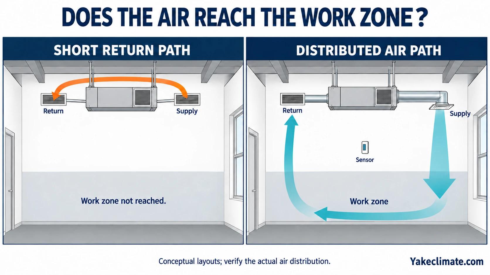
Three layout checks:
Separate supply and return paths where needed. Check whether the proposed outlets draw air through the intended zone or allow a short route back to the inlet. Separation distance alone does not demonstrate effective distribution.
Check outlet direction and throw against the space. Use the proposed diffuser and airflow data, then verify distribution after installation. Avoid obstructions and unintended drafts at the working or growing zone.
Choose representative sensing. A return sensor may be suitable when the return air represents the controlled zone; otherwise evaluate a compatible remote sensor. Confirm its location with the control design and compare it with room readings.
Several units may help serve separate zones, but unit count does not guarantee uniformity. Compare the proposed air paths, controls, service access and total capacity against a single ducted arrangement before choosing the layout.
Airflow, Ductwork and External Pressure
If discharge or return is ducted, the unit's available external static pressure becomes a hard constraint.
Obtain the manufacturer’s fan data for the intended configuration. Airflow and external static pressure must be evaluated together at the required operating point; two separate catalogue figures do not establish that point or an allowable duct length.
Coordinate the duct system with equipment selection. Additional resistance can change airflow, moisture removal and outlet throw. Check the installed operating point against the manufacturer’s permitted range instead of assuming the rated airflow survives any duct layout.
Practical checks:
- Calculate losses through ducts, fittings, dampers, outlets and external filtration at the design airflow; establish which internal losses are already included in the equipment data.
- Confirm the required airflow is available at that total external resistance, using the applicable fan curve or manufacturer confirmation.
- Include the specified filter-loading allowance and confirm how airflow will be checked as filters become dirty.
- Use pressure-loss data for the actual duct type, size and installation. Flexible duct compression, bends and poor routing can add resistance.
Where a long distribution run is genuinely needed, a ducted unit designed for higher external pressure is a different product selection, covered in ducted dehumidifier systems.
Drainage From Height
Plan the route from the overhead drain pan to an approved discharge point, including the consequences of leakage on the space below.
Check a gravity route first. Confirm the manufacturer’s required fall, available height and clearance around beams and other services. A route that fits on plan may not leave enough vertical space for the drain detail.
Use the model’s drain detail. Pan pressure can affect drainage. Verify the manufacturer’s trap geometry and pressure allowance for the actual arrangement, including priming and the required drain fall. Check operation in all intended fan modes; one generic trap-depth rule is not a complete design.
If a condensate pump is needed, select it for the flow and lift. Agree overflow detection, alarm and shutdown responses with the project team, and test them during commissioning.
Freeze protection where the drain run passes through unheated space.
Provide cleaning access to the pan and trap. Debris or growth can obstruct drainage; accessible components support inspection and maintenance before an overflow develops.
Consider what is below. In a food processing area, a growing space or over electrical equipment, the consequence of a drain failure sets how much redundancy and detection is justified.
Service Access Is Part of the Design
Overhead equipment needs a practical maintenance route. A service panel that can open is insufficient if personnel cannot safely reach it or remove the components behind it.
Plan access for these tasks; set intervals from the model instructions and site conditions:
| Item | Maintenance task | Access requirement |
|---|---|---|
| Filters | Inspection and replacement as specified | Removable without dismantling the unit or dropping ceiling |
| Coil faces | Periodic inspection and cleaning | Sufficient clearance to reach both faces |
| Drain pan and trap | Periodic cleaning | Reachable and visible |
| Fan and motor | Periodic inspection | Clearance for removal |
| Controls and electrical | As required | Safe working position |
Practical provisions:
- Clearance on the access side, specified from the equipment data rather than assumed. Ceiling void depth frequently gets consumed by other services after the mechanical layout is set.
- A safe working platform or access route. Where access requires a lift, that determines what is below the unit — a unit above fixed process equipment or a planted bed may be effectively unreachable.
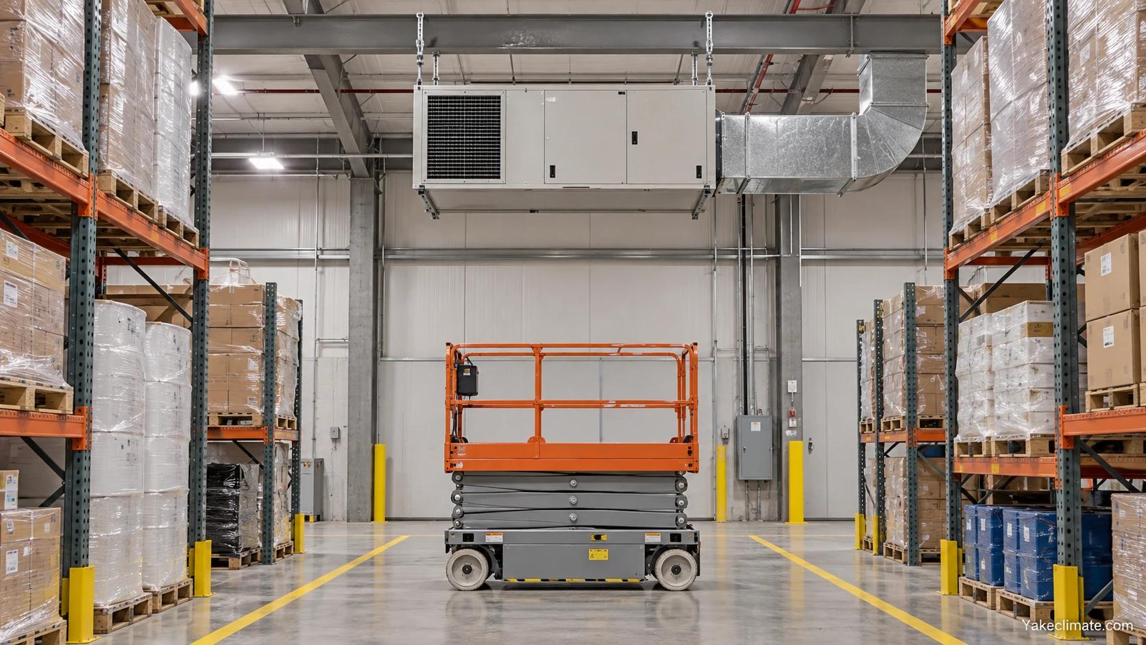
- Provide safe isolation. Agree electrical isolation and any drainage service procedure with the installers, including the effect on connected equipment and the occupied space.
- Arrange convenient filter access where compatible with the model. Confirm removal clearance and safe handling without assuming every unit can be serviced from below.
Plan service access around the inspection and cleaning tasks described in commercial dehumidifier maintenance. Follow the actual model’s instructions and site maintenance plan.
Noise
Request model-specific acoustic data and its measurement conditions. A catalogue sound figure alone does not establish the sound level at a person’s position in the completed room.
Points to check:
- The measurement condition for the stated figure — distance and whether free-field or in a room.
- The requirement for the space, and whether it applies during occupied hours only.
- Whether ductwork carries noise to other areas, and whether attenuation is needed.
- Check structure-borne transmission through mounts, hangers and connections as well as airborne sound from the unit and ducts.
Set the acoustic acceptance criteria for the actual space, including occupied areas and adjacent rooms. Do not assume a greenhouse or warehouse has no noise constraints.
RYDZ-7S — Industrial Ceiling Dehumidifier Review this model as an equipment option. Confirm current capacity and its rating conditions, dimensions, operating weight, fan data, drain detail and service clearances before specifying the installation.
RYDZ-138DM — Industrial Ceiling Dehumidifier Review this model as an equipment option. Confirm current capacity and its rating conditions, dimensions, operating weight, fan data, drain detail and service clearances before specifying the installation.
Coordination and Installation Sequence
Coordinate the equipment interfaces before installation, then verify their operation during commissioning.
- Reserve the mechanical layout and service envelope alongside ducts, cable trays, sprinklers, lighting and bracing. Resolve clashes before the ceiling is closed.
- Confirm the drain route with the plumbing design, including fall and trap position, before the ceiling is closed.
- Confirm the structural provision with the structural engineer before fixings are set.
- Agree the control sensor position and sequence with the controls contractor. Verify that its readings represent the intended zone under the operating modes being commissioned.
- Record the installed duct layout, sensor position and drain arrangement. During commissioning, verify airflow and pressure, compare room and return readings, demonstrate drainage in the intended fan modes, and test specified alarms and interlocks. Record conditions and acceptance results for later diagnosis.
Information to Prepare
- Space dimensions, ceiling height, void depth, and structure available for fixing.
- Moisture load and target condition, and the design entering-air condition — see commercial dehumidifier selection.
- Whether discharge and return will be free or ducted, and the intended duct layout with lengths and fittings.
- Available drain point, its level, and the route from the intended unit position.
- Confirm the selected model’s voltage, phase, frequency, electrical protection and isolation requirements against the available supply.
- Access arrangements: how the unit will be reached, and what is below it.
- Noise requirement for the space.
- Control system and intended sensor position.
- Other services competing for the ceiling void.
- Environment: humidity, washdown, corrosive atmosphere or food-contact adjacency.
Discussing a Project
Yakeclimate designs and manufactures industrial dehumidification equipment for complex climate applications, with a focus on agriculture and energy projects.
We co-develop application-specific dehumidification equipment around the operating conditions, interfaces, and integration requirements of the wider project or system.
Structural design, ductwork design and drainage design remain with the project's engineers. Our scope is the equipment and its interface requirements — weight, dimensions, airflow, external pressure, drain connection, power and control.
Review industrial ceiling dehumidifiers, explore commercial ceiling dehumidifiers, or contact Yakeclimate with the operating conditions and interface requirements for your project.
FAQ
Frequently Asked Questions
What structural provision does a ceiling dehumidifier need?
Have the structural engineer verify the load path, fixing locations and applicable operating, installation and maintenance loads using current model data. Purlins are not automatically unsuitable, but their capacity for the proposed load must be checked. Coordinate vibration isolation and provide a safe maintenance route rather than treating the unit casing as a platform.
Why does my ceiling dehumidifier satisfy its sensor while the room stays humid?
Short-circuiting is possible, but the symptom alone does not establish it. Compare simultaneous room, return and supply temperature and humidity readings; check sensor accuracy, operating state and airflow paths. Use those findings to decide whether distribution, sensing, equipment operation or another moisture source needs attention.
Can I duct a ceiling dehumidifier?
Only where the model supports the proposed arrangement. Match the required airflow to the total external resistance using applicable fan data, including fittings, outlets and filter-loading allowance. Separate catalogue airflow and pressure figures do not prove a matched operating point or a maximum duct length.
Why won't the drain pan drain?
Check for blockage, incorrect fall, pump problems and pressure effects. Use the manufacturer’s complete drain and trap detail for the actual pan pressure, with required priming and clearance. Test drainage in all intended fan modes; do not diagnose the fault or size the trap from a single depth rule.
How much access clearance should be allowed?
Use the selected model’s service drawings. Allow removal clearance for filters and replaceable components, access to coil faces, and inspection of the pan and trap. Also reserve a safe working position and an unobstructed route for a lift or platform where required.
Ceiling or floor-standing?
Compare the available floor area with the overhead support, distribution, drainage and access requirements. Floor mounting can simplify access but still needs suitable support and drainage. Ceiling mounting is a practical option when its interfaces can be resolved for the project; neither arrangement is universally preferable.


