
A smart greenhouse climate-control system is not one controller or one piece of equipment. It is a chain of responsibilities: the grower or agronomist defines crop and production objectives; the supervisory climate computer coordinates heating, ventilation, screens, lighting, irrigation, CO₂ and humidity actions; field devices execute commands and report status; and commissioning verifies that the whole chain produces representative conditions in the crop zone.
Projects become difficult when those responsibilities are left implicit. A dehumidifier can remove water from air, but it should not silently decide the crop strategy. A climate computer can request humidity control, but it cannot create verified dehumidifier capacity at an unspecified entering-air condition. A sensor can send a number, but it cannot prove that the number represents the whole greenhouse.
The purpose of the interface plan is to make each boundary explicit before equipment is selected.
Start with the crop objective, not the device list
The grower or crop specialist should define the biological and operational requirements:
- crop, cultivar, growth stage and production schedule;
- day/night temperature strategy and allowable excursions;
- humidity, dew-point, VPD or leaf-wetness risk objective;
- irrigation, lighting and CO₂ schedules that change moisture generation;
- disease-management and sanitation constraints;
- zones that must be controlled separately;
- what happens during alarms, maintenance or loss of communication.
These are not dehumidifier settings by default. They are inputs to a wider control strategy. The supervisory system decides how available actions are sequenced to meet them while respecting energy, equipment and safety constraints.
For an overview of where mechanical moisture removal fits alongside ventilation and heating, use greenhouse dehumidification: where it fits and how it is sized.
Responsibility matrix
| Decision or task | Primary owner | Required collaboration |
|---|---|---|
| Crop targets and acceptable excursions | Grower/agronomist | Climate-control designer |
| Zone strategy and control sequence | Greenhouse controls/HVAC integrator | Grower and equipment suppliers |
| Sensor type, location and calibration plan | Controls/commissioning team | Grower and equipment suppliers |
| Moisture-load and entering-condition brief | Project/HVAC engineer | Grower and dehumidifier manufacturer |
| Equipment performance and operating envelope | Equipment manufacturer | Project engineer |
| Command, status and alarm point list | Controls integrator | Equipment manufacturer and operator |
| Power, ducts, drains and service access | Project installation team | Equipment manufacturer |
| Functional testing and trend review | Commissioning authority/project team | All responsible parties |
| Crop-response validation | Grower/agronomist | Controls team |
| Ongoing maintenance and alarm response | Site operator | Equipment/service suppliers |
Yakeclimate’s role is to design and manufacture application-specific dehumidification equipment around confirmed operating conditions, interfaces and integration requirements. It does not replace the greenhouse controls integrator, crop specialist or project commissioning authority.
Sensor inputs: one reading is not a climate map
USDA Agricultural Research Service work using multiple wireless sensors found that greenhouse temperature and relative humidity varied over both time and space. Wageningen research using dense sensor networks in commercial greenhouses likewise documented spatial heterogeneity. The practical lesson is straightforward: sensor location and representativeness are control inputs, not minor installation details.
At minimum, the monitoring design should consider:
Air temperature and RH in the crop zone. Shield sensors from direct radiation and avoid placing the control sensor in the dry-air jet, next to a heater or immediately beside a wet pad.
Outdoor temperature and moisture condition. Ventilation decisions need outdoor humidity ratio or dew point, not only outdoor RH. Ventilation can remove moisture only when the incoming air carries less water than the air being exhausted.
Surface or leaf-temperature proxy where condensation matters. Air RH alone does not show whether a cold glazing surface, screen, pipe or leaf is below dew point.
Equipment and airflow status. Fan proof, damper position, heater state, dehumidifier state, filter alarm and drain alarm help distinguish a control problem from an equipment problem.
Process context. Irrigation events, lighting level, screen position, CO₂ dosing and door events explain moisture changes. Without these states, a humidity trend can be misdiagnosed.
Use multiple representative points in large, divided or high-density houses. A practical strategy is to designate control sensors, monitoring sensors and temporary commissioning sensors separately so that not every point is allowed to drive the loop.
Control outputs must be coordinated
Humidity cannot be controlled independently from temperature, air movement and crop operation.
| Control action | Moisture effect | Other consequence that must be coordinated |
|---|---|---|
| Ventilation | Removes moisture only when outdoor air is drier on an absolute basis | Heat and CO₂ loss; weather dependence |
| Heating | Lowers RH at the same water content | Does not remove water; may increase energy use |
| Air circulation | Reduces local gradients and supports surface drying | Does not remove water from the greenhouse |
| Mechanical dehumidification | Condenses or adsorbs water independently of outdoor moisture | Adds heat or needs regeneration; requires drainage/exhaust |
| Screen movement | Changes heat loss, mixing and surface temperatures | Can create a cold, humid zone above or below the screen |
| Irrigation timing | Changes when water enters the crop/air system | Must remain compatible with crop strategy |
| Cooling/fogging | Can change temperature and water content together | May conflict with humidity removal if uncoordinated |
A good sequence defines priorities and lockouts. For example, the supervisory controller should not command full ventilation for humidity while simultaneously expecting CO₂ enrichment to hold its setpoint. A dehumidifier should not run against an unintentional open vent without the project explicitly accepting that mode. Heating used to avoid a cold surface should be coordinated with ventilation or dehumidification if actual water removal is also required.
The correct sequence varies by climate, season, crop and equipment. The project should document it as a state table rather than rely on informal operator knowledge.
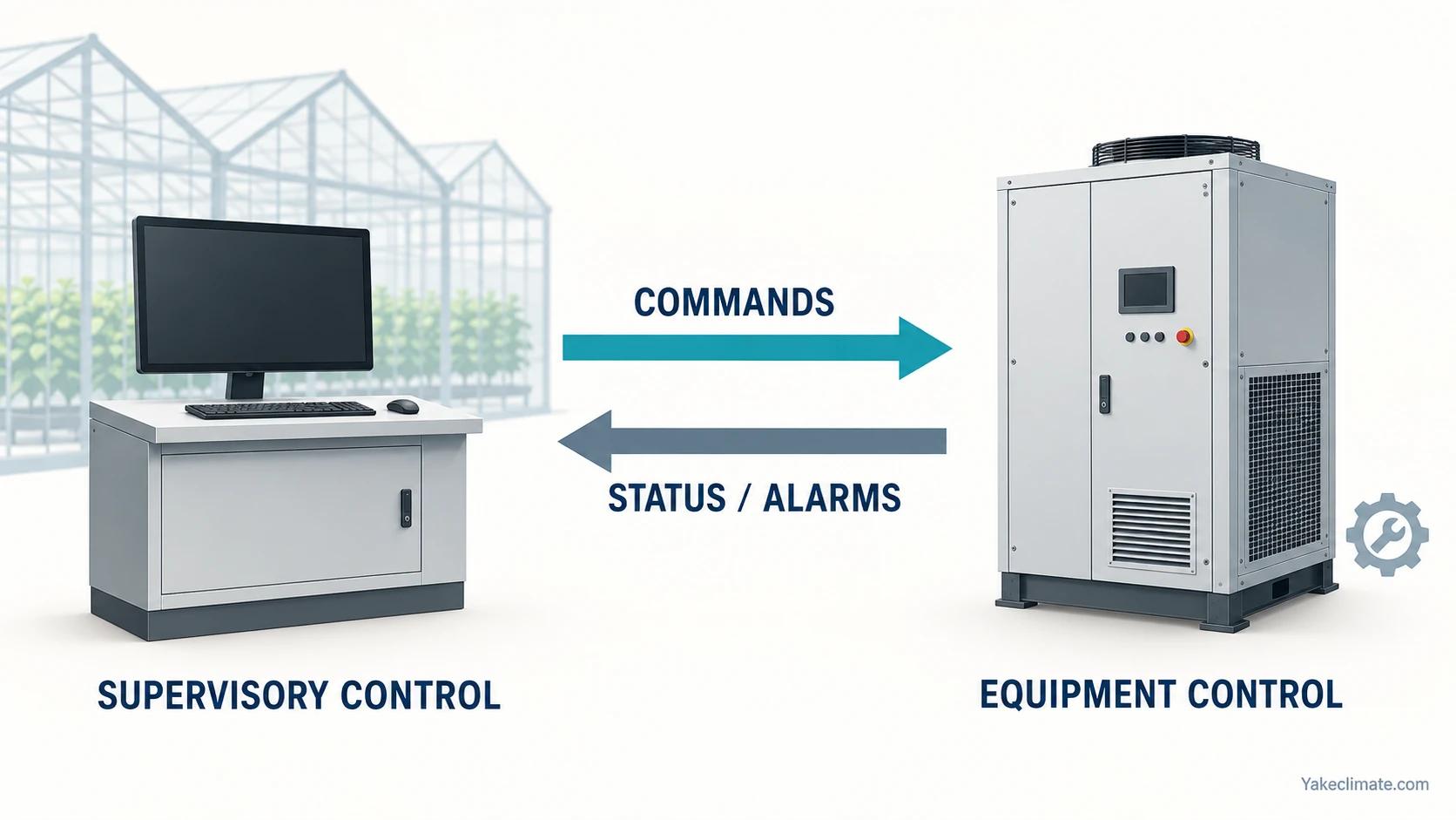
What the dehumidifier interface should contain
Do not begin with a protocol name. Begin with the decisions the supervisory system actually needs to make and the states the operator needs to see.
Minimum command set
- enable/disable or run request;
- local/remote mode where supported;
- target or stage request only if the selected controller supports it;
- reset request only where safe and documented.
Minimum status and alarm set
- available/ready;
- running or stage status;
- general alarm plus specific actionable alarms where available;
- sensor fault;
- drain or high-water fault where applicable;
- communication status;
- maintenance/filter indication where supported.
Data points that may be useful
- local temperature and RH;
- calculated dew point if the calculation basis is documented;
- runtime and starts;
- fan/compressor or regeneration state;
- local setpoint and actual control mode.
This is a functional point list, not a promise that every Yakeclimate model exposes every point or protocol. Confirm the exact electrical interface, signal type, register map and failure behaviour for the selected configuration before ordering.
Define control authority and failure behaviour
Every commandable setpoint needs one source of truth. If both a local controller and the greenhouse computer can change the target, define which has priority in remote mode, what happens after a restart and how an operator can safely take local control for maintenance.
Record at least:
- command source in each mode;
- behaviour after power loss and communication loss;
- safe fallback if a sensor is invalid;
- minimum on/off time and stage delay;
- alarm latching and reset rules;
- whether loss of the supervisory signal stops, holds or locally controls the unit;
- who is notified and what action they take.
These rules are part of the controls design. They should not be improvised during final commissioning.
Prepare the equipment selection brief
The dehumidifier manufacturer needs conditions, not only greenhouse area:
- Greenhouse dimensions, compartments and screen arrangement.
- Normal and peak day/night temperature and moisture conditions.
- Control objective and allowable excursion.
- Irrigation minus drain, or another defensible moisture-load estimate, is a preliminary value to check against crop retention, growing-medium storage, evaporation, drainage timing and other water flows before assigning it to a control loop.
- Outdoor design states and intended ventilation strategy.
- Lighting, CO₂ and production schedules.
- Required recovery time after transitions or events.
- Air-distribution concept and duct/static-pressure requirements.
- Drain route, power, installation and service constraints.
- Required commands, status, alarms and communication interface.
- Redundancy and acceptable downtime.
- Commissioning and acceptance measurements.
Use the greenhouse design-data checklist to define the water-balance boundary, load interval and rating conditions before assigning an equipment duty.
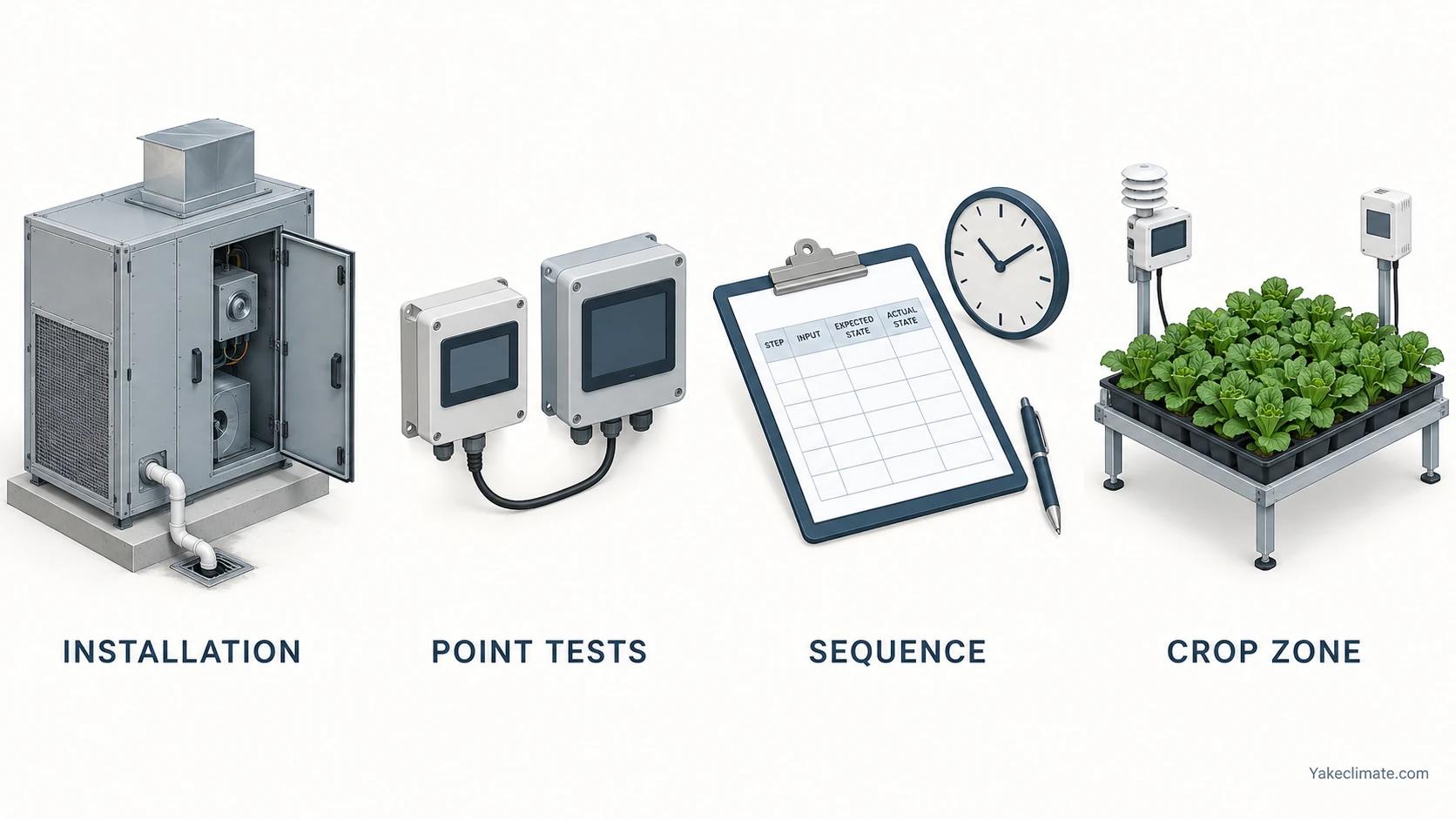
Commission in four layers
Layer 1: installation verification
Verify power, protection, supports, ducts, airflow direction, filters, condensate drain, traps, access and sensor placement against the approved documents. Confirm that dampers, screens and doors are in the assumed state.
Layer 2: point-to-point and failure testing
Command every available state and verify feedback at both the equipment and supervisory system. Simulate sensor failure, communication loss, alarm and restart according to the approved sequence. Confirm units and scaling for analogue values and registers.
Layer 3: functional sequence testing
Create conditions that call each stage. Verify priorities, minimum run times, lockouts and transitions. A functional test checks behaviour, not only whether a fan or compressor starts.
Layer 4: environmental and crop-zone validation
Trend representative crop-zone points together with outdoor moisture condition, equipment states, irrigation, lights and screens. Review spatial spread as well as average RH. Where condensation is the risk, include critical surface temperature or a defensible proxy and compare it with dew point.
Wageningen’s greenhouse-control research emphasizes that climate strategy is a coordinated optimization problem involving crop response and energy, which is why equipment-on testing alone is not a complete acceptance test.
A practical trend package
Usable greenhouse trends connect the crop-zone objective, the controller’s request, the resulting output, independent equipment feedback and the environmental response on a common time axis. Before changing a control setting, confirm what each point means, when it was recorded, and whether its value is representative of the zone. Choose a recording interval that can show the event under review, align the clocks, and run a short trial capture. A request or output alone does not prove that equipment was running when independent feedback is unavailable. Read day and night modes as recorded states, and treat an apparent delay as a question about the approved project sequence rather than as a universal equipment property.
Record the points, then make their meaning explicit
For each zone, record crop-zone air temperature and RH; outdoor temperature, RH or dew point; a surface or leaf-temperature proxy; ventilation, heating, circulation, screens, lighting, irrigation, CO₂ and dehumidification actions; equipment run and alarm states; door or other operational events; and condensate volume where practical. Add the active control mode, day/night state, relevant target or stage request, and the point definition used in the export. Record units, source, zone, status and whether a value is a command, controller output/state, proof of operation or environmental measurement.
Prepare the capture before reading the event
Check that controller, logger and stand-alone instruments use known clocks and document any offset. Confirm column names, units, scaling, zone labels and missing-value behaviour. A trial capture can expose stale points or an export that omits the relevant state. Keep a missing or ambiguous value unknown; do not fill it with an inferred operating state.
Read night events and repeated requests as a sequence
Check the configured dead-band or hysteresis, stage-change delay and restart delay against the approved sequence. Record how the selected controller defines each term, the trigger for each timer and the permitted output response. A request may precede an output change, but its timing must be evaluated against that configuration rather than a universal delay.
| Observed record | What to check next | What it does not establish |
|---|---|---|
| Logs from different devices do not align | Clock settings, offsets and sampling context | It does not establish response delay |
| A command is on but no independent run feedback is available | Point meaning, available status, mode, alarms and the approved delay sequence | It does not establish that the equipment has failed |
| Repeated requests appear while RH moves up and down | Request versus output and feedback, plus the configured dead-band, stage and restart logic | It does not establish a short-cycling root cause |
| Response changes after a day/night, screen, lighting, door or other operational event | Align the event and actual mode, then compare the environmental trend | It does not establish that one action caused the change |
The useful handoff is a raw trend excerpt with timestamps, point definitions, units, mode, alarm states, triggering event and approved sequence. Give it to both teams. See automated greenhouse humidity control systems.
Common boundary failures
The grower asks the equipment to choose crop targets. Resolve targets with the crop specialist and controls designer before translating them into equipment requirements.
The integrator assumes catalogue capacity applies at night. Request performance at the specified entering-air condition.
The equipment supplier assumes a dry contact completes integration. The project still needs control authority, alarm meaning, failure behaviour and commissioning.
One favourable sensor proves success. Review representative points and risk surfaces, not only the controller’s nearest sensor.
Heating is treated as water removal. Heating changes RH but does not remove water. See winter greenhouse humidity and condensation for the full boundary.
FAQ
Frequently Asked Questions
Who should set greenhouse humidity targets?
The grower or agronomist should define the crop and production objective. The controls designer translates it into a coordinated sequence, and equipment suppliers confirm what their devices can deliver at the specified conditions.
Can a dehumidifier control the whole greenhouse by itself?
It can remove moisture and may provide local control, but greenhouse climate also depends on heating, ventilation, screens, air movement, irrigation, lighting and crop load. Supervisory coordination remains a project-level responsibility.
How many humidity sensors does a greenhouse need?
There is no universal count. Use enough representative points to detect meaningful spatial differences across zones, canopy conditions and equipment influence, then designate which points control and which only monitor.
Should the greenhouse computer send an RH setpoint to the dehumidifier?
Only if the selected equipment and control sequence are designed for that arrangement. A simple enable/stage request can be clearer in some systems. Define authority, scaling and loss-of-communication behaviour either way.
What proves that commissioning is complete?
Verified installation, point-to-point tests, failure-mode tests, functional sequence tests and representative environmental trends under an agreed operating case. Equipment running is necessary but not sufficient.
Sources
- USDA ARS: Multi-point measurement of environmental conditions in a commercial greenhouse — temporal and spatial variation in greenhouse measurements.
- Wageningen University & Research: Using a wireless sensor network to determine climate heterogeneity — dense monitoring in commercial greenhouses.
- Wageningen University & Research: Optimal control of greenhouse climate — coordinated climate and energy control context.
- Wageningen University & Research: Heating and dehumidification in production greenhouses — comparison context and the absence of one universal dehumidification route.


