
Industrial dehumidifier control is not only a thermostat-style setpoint. The control design has to define the humidity variable, sensor location, staging logic, alarm outputs and communication method before the unit can be integrated with a BMS, PLC, greenhouse computer or local controller.
For the wider equipment route, connect the controls plan to the industrial dehumidifier product family, the industrial dehumidification resource page and the commercial dehumidifier selection guide.
Start With the Control Objective
The control objective should describe the risk being managed.
| Risk | Better control variable |
| General storage humidity | Relative humidity at room temperature. |
| Condensation on cold surfaces | Dew point below the surface temperature. |
| Low-temperature storage | Dew point or absolute moisture content. |
| Process drying | Moisture removal rate, outlet air condition or product moisture target. |
| Greenhouse disease risk | RH, dew point and sometimes VPD by operating period. |
| Electrical cabinet protection | Enclosure temperature, dew point margin and cabinet humidity. |
ASHRAE's psychrometrics training emphasizes moist-air properties and the analysis of HVAC components such as dehumidifiers. In practice, that means the control target must match the physical risk. Holding 50% RH in a warm room is not the same moisture condition as holding 50% RH in a cold room.
Decide Where the Sensor Belongs
Sensor location is a frequent cause of poor humidity control. A sensor inside the equipment return may give stable readings while the process zone still has wet spots. A sensor near a door may chase every air leak. A sensor above a crop canopy may miss condensation below a screen.
| Sensor location | Use it when | Watch for |
| Room reference point | The room is well mixed and the process is not local. | Stratification and door influence. |
| Return air | Equipment should react to the air returning to the unit. | It may not represent remote corners. |
| Supply air | Outlet condition must be verified. | It should not be the only room-control sensor. |
| Duct sensor | The system is ducted and balanced. | Poor duct mixing can distort readings. |
| Process zone | The product, crop or equipment has a local humidity risk. | Sensor protection and maintenance. |
| Cabinet or enclosure | Condensation risk is inside an electrical space. | Sensor response may lag room changes. |
For greenhouse projects, align the sensor plan with the responsibilities and interfaces in smart greenhouse climate control.
Define Local Control and External Enable
Industrial units can run as standalone machines, as part of a staged equipment group or under an external controller. The RFQ should state which mode is expected.
| Mode | Typical use | Required information |
| Local controller | Simple room or storage application. | Setpoint, deadband, sensor location and alarm output. |
| Remote enable | Existing system decides when the unit runs. | Dry contact logic, safe restart and fail state. |
| Analog demand | External controller sends a demand level. | Signal range, scaling and response behavior. |
| Multi-unit staging | Several dehumidifiers share a load. | Lead-lag, rotation, delay timers and alarm bypass rules. |
| Network integration | BMS, PLC or greenhouse computer needs data. | Protocol, register map, points list and permissions. |
The design should also define what happens when the external signal fails. A good sequence states whether the unit should stop, continue in local mode or alarm for operator action.
Compare mode definitions in the continuous versus demand-controlled dehumidification guide.
Specify Alarms Before Wiring
Alarm requirements should be practical. Too few alarms leave the operator blind; too many nuisance alarms are ignored.
| Alarm or status point | Why it helps |
| Unit run status | Indicates the operating state defined by the selected device; distinguish it from a command. |
| General fault | Gives a simple summary for BMS or PLC. |
| High humidity alarm | Reports that the defined monitored point meets the configured humidity-alarm condition. |
| Low temperature or freeze protection | Reports the selected device’s defined temperature-limit or protection state; verify the configured response separately. |
| Condensate overflow | Reports a water-level or drainage condition that needs the agreed equipment response or operator action. |
| Filter or airflow warning | Helps maintain capacity and coil performance. |
| Compressor, fan or reactivation fault | Speeds maintenance diagnosis. |
| Communication loss | Reports loss of the expected supervisory data so the agreed response can be initiated. |
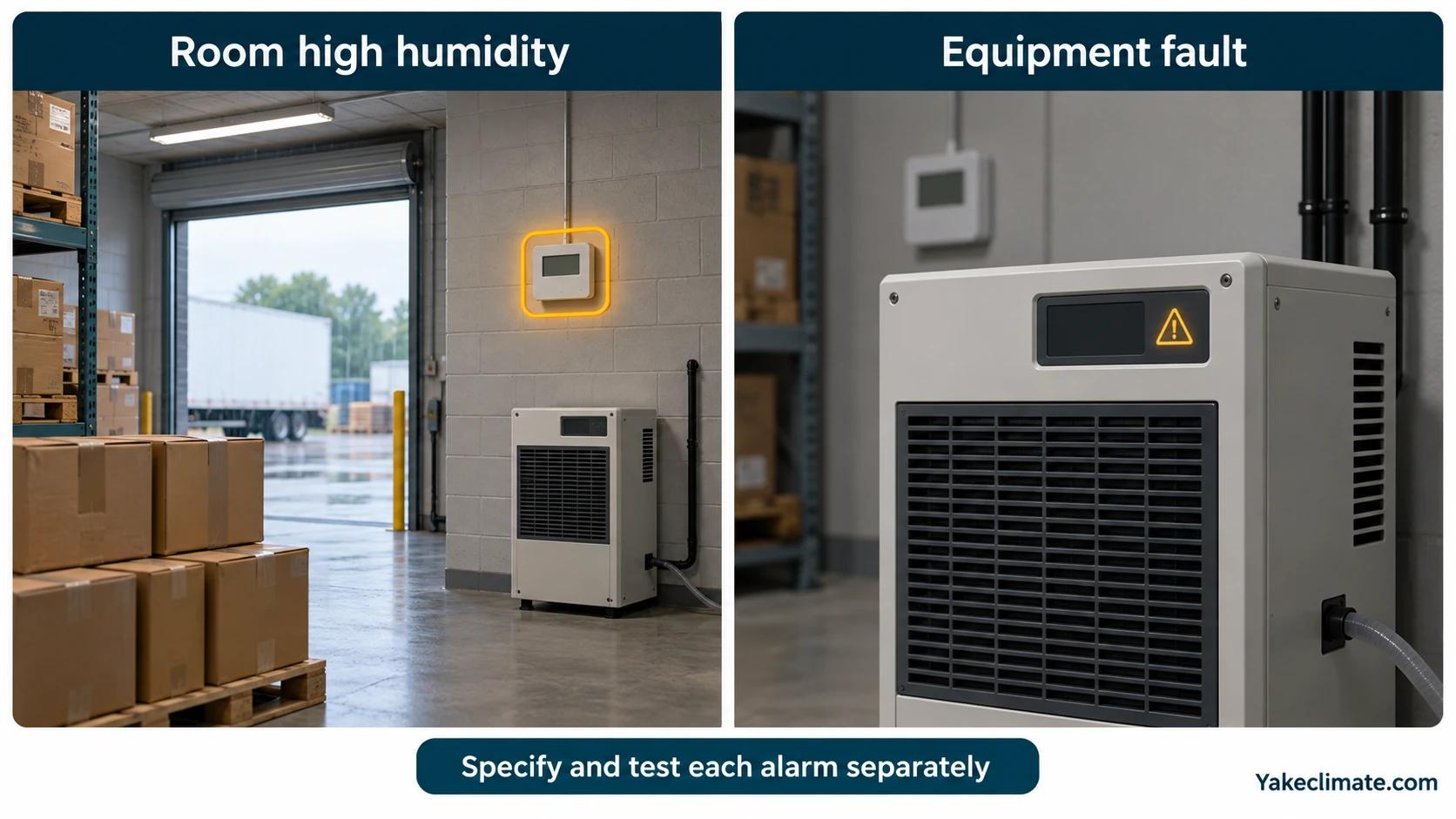
For a storage or process room, a high-humidity alarm should not be the same as a unit fault. The room can be wet even when the machine is healthy if the door, ventilation or process load changes.
Modbus, BACnet, Dry Contact or Analog?
The interface should be chosen based on the controller that will own the sequence.
| Interface | Best use | Specification detail |
| Dry contact | Enable, fault, simple alarm. | Normally open or normally closed logic. |
| 0-10 V or 4-20 mA | Demand signal or measured value. | Scaling, minimum speed and fail behavior. |
| Modbus RTU or TCP | PLC or industrial controller point exchange. | Device address, baud rate or IP, register map and data type. |
| BACnet | Building automation systems. | BACnet/IP or MS/TP, object list and write permissions. |
| Custom gateway | Existing site network has special requirements. | Who supplies and maintains the gateway. |
The Modbus Organization publishes the Modbus application protocol specification and implementation guides. ASHRAE's BACnet Standard 135 resource page describes BACnet as a communication protocol for monitoring and control of HVAC&R and other building systems. Those standards help define the language, but the project still needs a points list: exactly which values will be read or written.
Build a Practical Points List
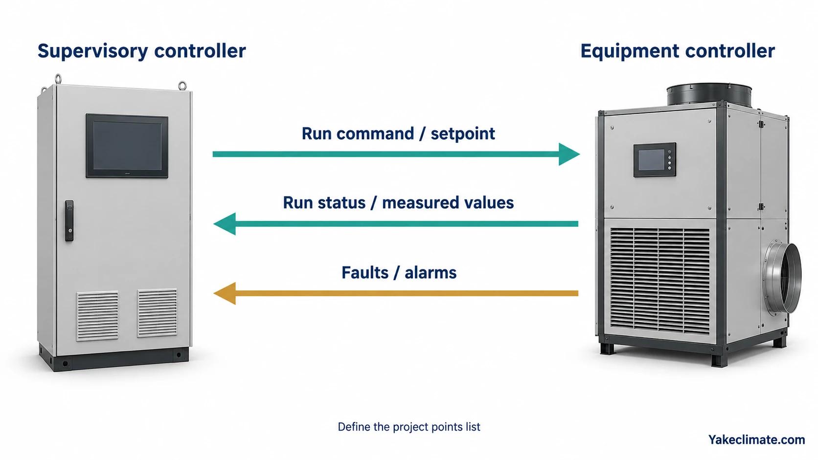
For most industrial dehumidifier projects, a useful points list includes:
- run command,
- run status,
- general fault,
- room humidity or return humidity,
- room temperature or return temperature,
- setpoint,
- high humidity alarm,
- condensate alarm,
- fan status,
- compressor or reactivation status,
- filter or airflow warning,
- accumulated runtime.
If the plant needs maintenance traceability, add trend data for power input, inlet and outlet condition, fault history and condensate rate where available.
Commission With Trend Data
A controls checkout should not stop after verifying that the display turns on. The system should be observed across load changes.
| Commissioning step | Evidence to keep |
| Sensor comparison | Handheld meter reading versus controller value. |
| Setpoint response | Trend showing humidity falling toward target. |
| Alarm test | Record of each alarm input and output. |
| Staging delay | Confirmation that units do not short-cycle together. |
| Door or process disturbance | Trend after a known load event. |
| Communication test | BMS or PLC screenshot with point names and units. |
For equipment selection before controls are finalized, start with the industrial dehumidifier specifications checklist. For interface planning, see connecting dehumidifiers to BMS and EMS.
Yakeclimate designs and manufactures industrial dehumidification equipment for complex climate applications. Include the required points list, controller interface and alarm behavior when you send the inquiry through the contact page.
FAQ
Frequently Asked Questions
Should an industrial dehumidifier control RH or dew point?
Use RH when the process risk is tied to relative humidity at a stable temperature. Use dew point when condensation, cold surfaces or low-temperature operation is the main risk.
Is Modbus better than dry contact control?
Modbus gives more data and more control points. Dry contacts are simpler and often enough for enable and fault signals. The better choice depends on the site's controller and maintenance capability.
Where should the humidity sensor be installed?
Install the main sensor where it represents the controlled risk. In a well-mixed room this may be a room reference point; in a ducted or process system it may need return, supply or local process-zone sensing.
What should be tested during commissioning?
Test sensor accuracy, setpoint response, alarm outputs, staging delays and the actual trend after a known humidity load. A one-time display reading is not enough.


