
1. Start With a Baseline
Condensate per running hour is condensate volume divided by runtime hours. Entering-air condition is the temperature and humidity of the air at the unit inlet.
Dehumidifier capacity can decline gradually and remain unnoticed. A complaint may be the first signal, but it is not proof of equipment failure; compare matched operating measurements with the commissioning baseline.
Without a commissioning reference, a humidity complaint alone cannot reliably distinguish a change in equipment performance from a change in the building moisture load. Measure both before choosing a corrective action.
A commissioning record gives later service teams a useful reference. Record the operating condition and measurements at the time of commissioning:
- entering air temperature and relative humidity at the unit's inlet;
- leaving air temperature and relative humidity at the outlet;
- airflow, measured rather than assumed;
- power input in kW;
- condensate rate over a measured period;
- filter pressure drop with clean filters installed;
- refrigerant circuit pressures and temperatures;
- control settings: setpoint, deadband, fan mode, any schedule;
- the date and the ambient conditions at the time.
A useful derived diagnostic measure to record is:
Condensate per running hour = condensate volume / runtime hoursCompare with the commissioning baseline at a similar entering-air temperature and RH, after checking controls, drainage and moisture storage. A changed collection rate is a diagnostic signal, not proof of equipment decline or a changed load from one reading. The reasoning is developed in how long should a dehumidifier run.
Without a baseline, later diagnosis is uncertain; a changed load and a fouled filter can require different corrective actions, so verify the operating evidence before adding equipment.
2. Operator Checks
These operator checks can reveal warning signals before they become larger capacity losses; refrigerant and other specialist work remains for appropriately qualified personnel.
| Item | Method | Warning signal |
|---|---|---|
| Filters | Judge by pressure drop, not appearance | Rising pressure drop; frosting in cold operation |
| Drainage | Confirm condensate is flowing | Overflow, lost collected water, float-switch shutdown |
| Readings | Compare display against an independent instrument | Sensor drift |
| Noise, vibration, airflow | Listen, feel, check discharge velocity | New noise, vibration, or low airflow |
| Ice on the coil | Inspect at conditions where frosting should not occur | Restricted airflow, refrigerant fault, defrost fault |
Check filter condition against pressure drop at comparable airflow and fan state. Compare with the clean-filter baseline and the equipment manufacturer's limit; appearance alone cannot establish whether airflow is adequate.
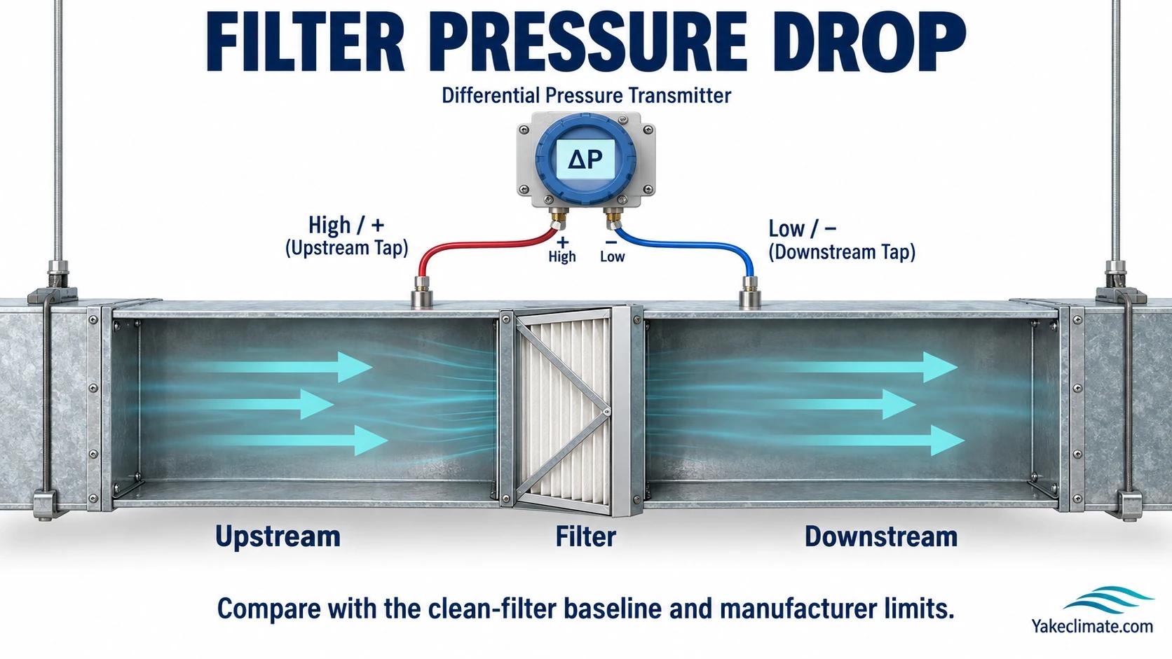
A restricted filter can change airflow and the operating point. On refrigerant equipment, evaluate any coil-temperature or frost concern against the entering-air condition, fan operation and defrost controls rather than assuming the same effect at every site.
3. Coils and Air Paths
Inspect the coil for fouling and drainage problems. Deposits on a wet evaporator can interfere with airflow and heat transfer; compare observed condition and measured performance with the equipment documentation before attributing a capacity complaint to the coil.
- Inspect both faces. Fouling on the leaving face is not visible from the entering side.
- Check fin condition. Bent fins restrict airflow locally and are easily missed.
- Clean appropriately for the fouling. Dry particulate, greasy deposits, and biological growth require different approaches. The wrong cleaning agent can damage fins or coatings.
- Address the source. A coil that fouls quickly indicates inadequate upstream filtration or a dusty environment.
- Drain pan and trap. Standing water and organic matter support biofilm, which blocks drains and produces odour. The pan needs to be reachable, a point secured at installation as discussed in commercial ceiling dehumidifiers.
4. Refrigerant Circuit
Refrigerant circuit work should be done by appropriately qualified personnel. Certification, handling and record-keeping duties depend on the refrigerant, equipment category, charge and jurisdiction, including any applicable exemptions.
- What operators should not do. Connect gauges, add refrigerant, or attempt repairs. Connecting gauges unnecessarily is itself a source of small losses.
- What a technician checks. Operating pressures and temperatures against the baseline, superheat and subcooling, compressor performance, and leak indications.
- Low charge is a symptom, not a root-cause diagnosis. Unexpected charge loss may indicate a leak or incomplete service history; check records and investigate before charging. Where the refrigerant is a fluorinated greenhouse gas, handling and recovery may be regulated.
- Leak-checking obligations. Duties depend on the refrigerant, equipment category, charge and jurisdiction. Applicable rules may include leak checks, recovery, records and technician requirements; Regulation (EU) 2024/573 is one EU framework, while other markets have their own rules.
- Flammable refrigerants change the service procedure. A2L and A3 refrigerants require service procedures, tools, and technician competence appropriate to that classification. See R290 vs. R410A in industrial dehumidification.
5. Desiccant Equipment
Desiccant machines have a different maintenance profile, and some items have no refrigerant-side equivalent.
- Rotor condition. The desiccant medium can be degraded by contamination, oil carryover, or exposure outside its design range. If inspection and the equipment documentation show that the desiccant medium has degraded, cleaning may not restore its rated performance; confirm the medium, contamination and replacement criteria for the specific machine.
- Seals. The seals separating the process and reactivation air streams can wear and permit cross-leakage, reducing moisture removal. Inspect and replace them using the specific machine's service criteria.
- Reactivation heater and controls. Reactivation temperature must reach and hold the design value stated in the specific machine documentation; do not substitute a generic temperature for that value.
- Reactivation exhaust path. A restricted exhaust reduces regeneration effectiveness and can allow moist exhaust air back into the process stream.
- Drive and belt. Rotor rotation speed affects performance; a slipping drive reduces capacity.
- Filters on both streams. Process and reactivation air both need filtration, and the reactivation side is often overlooked.
6. Sensors and Controls
Humidity-sensor readings can change with age, contamination or location. Compare the installed reading with an appropriate reference instrument at the same air condition and record the deviation against the project's tolerance; trend and redundant-sensor discrepancies are also reasons to investigate.

- Sensor location. Confirm the sensor is still where the design intended. Sensors get moved during other works.
- Settings. Setpoint, deadband, and schedule should be checked against design intent. Settings drift through operator adjustment.
- Alarm function. Test that failure alarms actually annunciate. A silenced or disconnected alarm leaves the installation unprotected.
7. Frequency: Condition-Based
Running hours and air cleanliness vary between installations. Use observed condition and comparable measurements to plan checks, while retaining the equipment manufacturer's required service limits and any applicable regulatory maximum intervals.
| Item | Trigger |
|---|---|
| Filters | Measured pressure drop, with a maximum interval as backstop |
| Coils | Inspection at an interval set from observed fouling rate |
| Drainage | Routine operator check; cleaning on observation |
| Refrigerant circuit | Jurisdiction leak-checking obligations plus performance-triggered investigation |
| Sensors | Verification interval matched to application tolerance |
| Performance review | Periodic comparison of condensate per running hour against baseline |
The periodic performance review is what catches decline before a complaint arrives.
8. Records That Are Actually Useful
A maintenance record that lists dates and signatures has limited diagnostic value. A record that supports diagnosis contains:
- the commissioning baseline, retained and accessible;
- date, operating condition, and observed performance at each visit;
- filter pressure drop at change, not just the fact of the change;
- condensate per running hour, periodically;
- refrigerant work: what was found, what was done, quantities involved;
- sensor verification results, including the deviation found;
- setting changes with the reason for them;
- faults and their resolution.
Where equipment is deployed across multiple sites, comparing these records across the fleet identifies design-level issues that no single site's record would reveal.
9. Information to Prepare for a Service Discussion
- Equipment model, installation date, and the commissioning baseline if available.
- Current symptoms, when they started, and whether they are seasonal.
- Logged space conditions and runtime.
- Condensate volume, currently and historically.
- Filter and cleaning history.
- Any changes to the space, process, ventilation, or occupancy since installation.
- Refrigerant service history.
- Sensor verification history.
10. Discussing a Project
Industrial Dehumidification for Complex Climate Applications
Yakeclimate designs and manufactures industrial dehumidification equipment for complex climate applications, with a focus on agriculture and energy projects.
We co-develop application-specific dehumidification equipment around the operating conditions, interfaces, and integration requirements of the wider project or system.
Refrigerant handling, leak checking, and technician certification requirements are set by the regulations in force where the equipment is installed, and refrigerant work should be carried out by appropriately qualified personnel.
Explore industrial dehumidifiers, review desiccant rotor dehumidifiers, or contact Yakeclimate to review the operating conditions for your project.
FAQ
Frequently Asked Questions
How often should a commercial dehumidifier be serviced?
Use condition-based observations within the equipment manufacturer's required service limits and applicable regulatory maximum intervals. Compare filter pressure drop at matched airflow and fan state with the clean baseline or OEM limit; inspect coils for observed fouling, check drainage routinely, and arrange regulated refrigerant work with appropriately qualified personnel. Review condensate collection only under matched entering-air and operating conditions; it is a diagnostic signal, not proof from one reading.
How do I know if capacity has degraded?
Compare condensate per running hour with the commissioning baseline at similar entering-air temperature and RH after checking controls, drainage and moisture storage. A changed result can guide investigation of equipment, ventilation or process load; it cannot prove a cause from one reading.
How should filters be judged?
Compare pressure drop at similar airflow and fan state with the clean-filter baseline and the equipment manufacturer's limit. Appearance alone is insufficient. If restriction is suspected, check actual airflow and the refrigerant unit's coil and defrost operation under the same entering-air conditions.
My dehumidifier needs refrigerant added — is that normal?
Not as a routine maintenance assumption. Unexpected charge loss may indicate a leak or incomplete service history, so check records and investigate before charging. Where the refrigerant is a fluorinated greenhouse gas, leak checking, recovery and technician duties depend on the refrigerant, equipment category, charge and jurisdiction.
What is different about maintaining a desiccant dehumidifier?
Inspect process/reactivation seals for cross-leakage, confirm reactivation temperature against the specific machine's design value, and check exhaust routing and rotor drive. If the desiccant medium is suspected of degradation, follow the manufacturer's inspection and replacement criteria; cleaning is not automatically sufficient.
Can humidity sensors be trusted indefinitely?
Humidity-sensor readings can change with age, contamination or location. Compare with a suitable reference instrument at the same air condition and against the project's tolerance; investigate control trends or redundant-sensor discrepancies, and confirm the installed sensor remains at its designed location.
References
- Regulation (EU) 2024/573 on fluorinated greenhouse gases — EUR-Lex
RY-750M — Desiccant Rotor Dehumidifier — 108 L/24h rated at 20°C, 60% RH; applicable temperature range −10 to +55°C. For desiccant maintenance, inspect rotor seals, reactivation temperature and exhaust routing against this machine's service instructions.


