
When an air-distribution tube supplies one end of a greenhouse well but leaves other areas stagnant, inspect distribution before assuming more dehumidifier capacity will solve the problem. Map where air arrives and compare the fan, tube and opening arrangement with the intended duty.
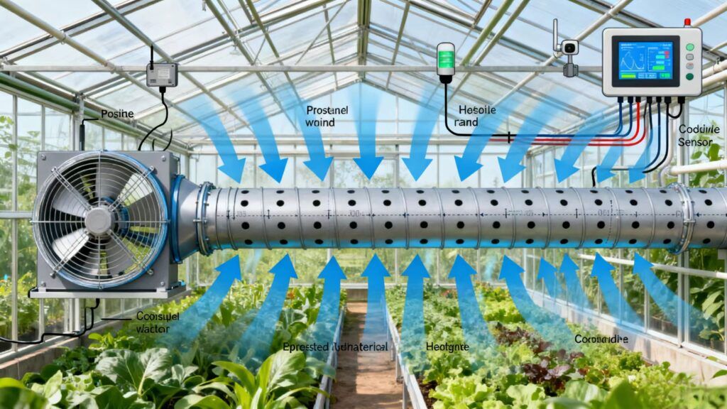
Tube performance depends on the fan operating point, pressure distribution, openings and installed geometry together.
Three Jobs, Frequently Confused
Distribution tubing is used for three functions that have different objectives, different sizing logic and different operating periods. Specifying one and expecting another is a recurring source of disappointment.
Ventilation exchanges indoor and outdoor air. Define heat, moisture and fresh-air duties separately. Moisture removal depends on the difference in water content between the exchanged streams; see ventilation versus dehumidification.
Circulation — mixing air inside the house. The objective is to eliminate stratification and stagnant zones without exchanging any air with outside. Sizing is driven by the volume that has to be kept in motion and by the velocity needed at canopy level. This function runs continuously in many facilities, including at night when ventilation is closed.
Distribution — delivering conditioned air. The objective is to carry air from a specific source — a heater, or a dehumidifier — to the positions where it is needed. Sizing is driven by the source equipment's airflow and by where the air has to arrive.
A tube may serve more than one duty if each operating mode is checked. Confirm airflow, available pressure, outlet direction and crop-zone delivery for the proposed source; a tube suitable for one duty is not automatically suitable for another.
Uniform Discharge Is a Pressure Problem
Flow through an opening depends on its effective area and pressure difference. With similar openings, similar pressure differences help produce similar discharge. Deliberately varied openings require their own design check.
Pressure along the tube reflects both losses and the change in axial velocity as air leaves through successive openings.
Friction dissipates total pressure along the air path. It does not alone predict the static pressure at each opening because axial flow and velocity also change downstream.
As air leaves through openings, downstream axial flow decreases. The associated change in velocity can affect static pressure, alongside friction and local losses. Assess the combined distribution using the tube geometry, hole pattern, fan curve and measurements.
The balance between these determines the outcome, and it is controlled by the relationship between the tube's cross-sectional area and the total open area of its holes.
If distribution is uneven, check opening geometry, tube inflation, fan operating point and pressure or discharge at several positions. Excess opening area is one possible contributor; a weak far end does not identify one cause by itself.
Restricted total opening area can alter the operating point and discharge velocities. Compare measured flow and pressure with the tube and fan limits before changing the opening pattern.
The correct proportion depends on tube diameter, length, hole size and pattern, and on the fan's pressure characteristic. Tubing suppliers publish design data covering these combinations, and the tube should be selected against that data for the specific fan and run length rather than by adopting a rule of thumb. A tube that works well at 30 m may perform poorly at 60 m with the same hole pattern.
Hole Pattern and Where the Air Goes
Obtain hole diameter and spacing from the system design for the stated material, flow, pressure, length and crop-zone duty. A transferable opening schedule cannot be selected from tube length alone.
Hole position around the tube's circumference is described by clock positions viewed along the tube — a "4/8" pattern places holes at the 4 o'clock and 8 o'clock positions, discharging downward and outward on both sides. Other common patterns such as 5/7 and 3/9 direct the air more steeply downward or more horizontally.
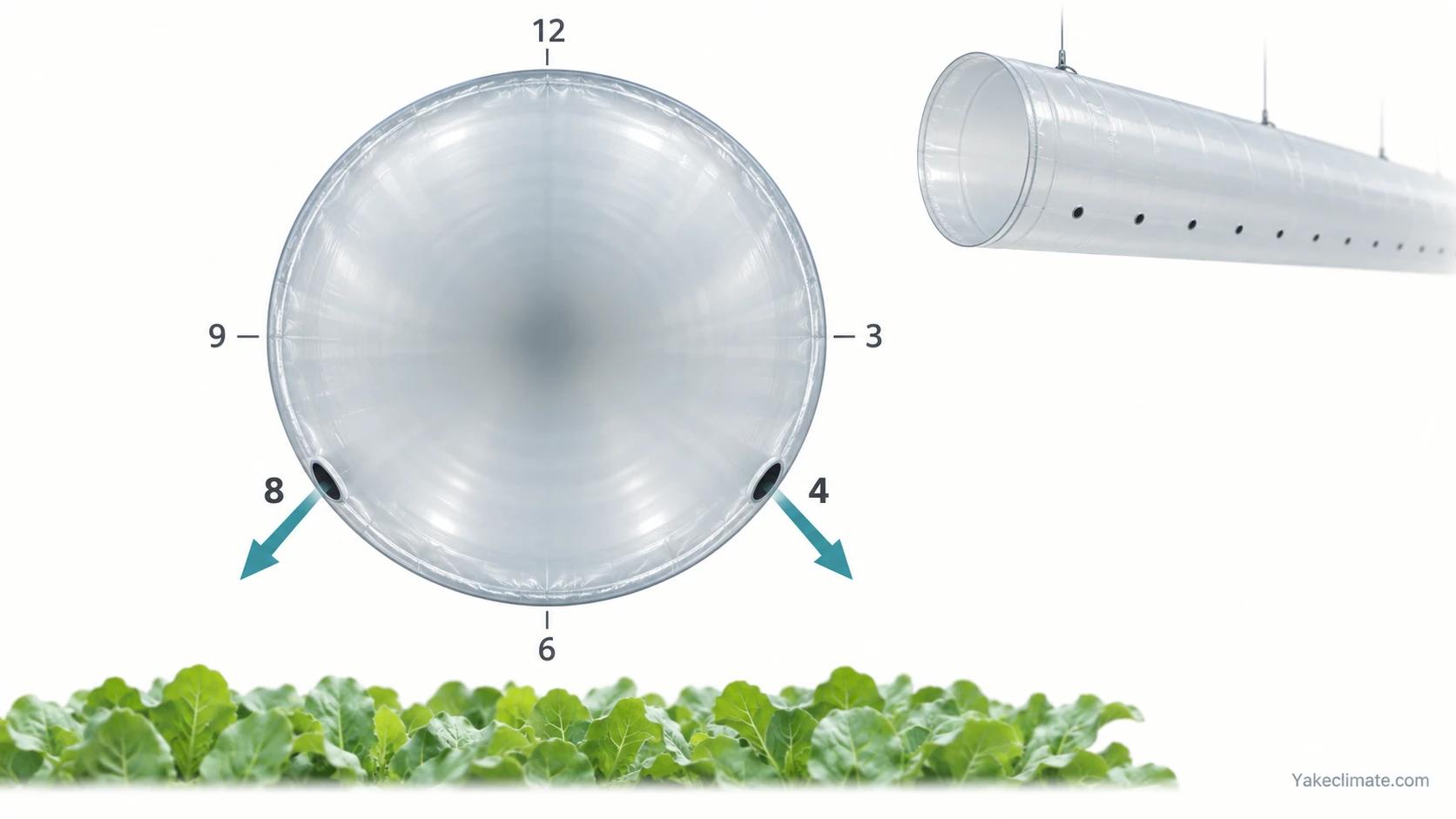
The pattern choice determines where the air actually arrives:
- Downward-angled patterns drive air toward the floor and into the crop. Useful for canopy circulation and for reaching under benches, but capable of causing plant movement or drying if the tube is close to the crop.
- Horizontal patterns throw air across the house, mixing the upper volume. Useful for destratification, less effective at penetrating a dense canopy.
- Upward patterns are used where the objective is to temper incoming cold air by mixing it with warm air at the ridge before it reaches the crop — a winter ventilation strategy rather than a circulation one.
For humidity management, check representative canopy locations as well as the upper air volume. A satisfactory reading above the crop does not establish that leaf-zone conditions are satisfactory.
Jets Move More Air Than They Carry
A useful property of hole discharge: each jet entrains surrounding air as it travels, so the volume of air actually set in motion is considerably greater than the volume passing through the tube.
This is why a relatively modest tube airflow can circulate a large house volume, and it is why jet throw — how far the jet travels before dissipating — matters more than the discharge rate at the hole.
It also means the tube's position relative to the crop is a design variable rather than a convenience. A tube mounted high delivers jets that entrain and mix a large volume but arrive at the canopy weakened. A tube mounted low delivers directly to the canopy but affects a narrower band. Facilities with a wide bay and a single high tube frequently find that the centre of the bay is well mixed and the outer rows are not.
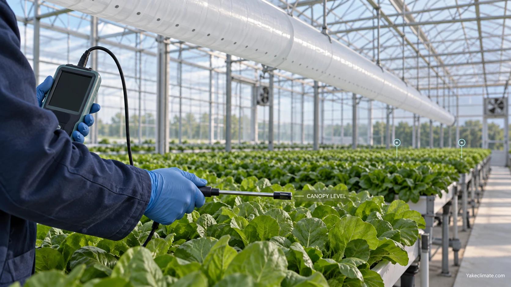
Measure air movement at representative crop locations and record instrument position, averaging interval, crop structure and operating state. Set acceptance criteria from the crop and project requirements rather than a universal canopy velocity.
Coordinating Tubes With Dehumidification Equipment
Where mechanical dehumidification is installed in a house that already has distribution tubing, the two air systems have to be designed as one.
Avoid short-circuiting. If the dehumidifier's return is close to a tube discharge, it will draw in air it has just conditioned rather than the humid air from the canopy. The unit will show excellent performance at its own sensors while the house stays humid.
Before connecting dehumidifier discharge, check its airflow and available external pressure against the tube rating, opening pattern and transition. Confirm the resulting fan operating point and distribution; an existing tube may be usable, may need modification, or may be unsuitable.
Match the operating periods. Circulation typically runs continuously; dehumidification runs on demand. If they share a tube, the control sequence has to account for what happens when one runs without the other.
Reinforce the existing pattern rather than fighting it. Tubes and horizontal airflow fans establish a circulation pattern. Dehumidification supply and return positions chosen without reference to that pattern can create new dead zones. The layout should be reviewed as a whole.
Four Common Failure Modes
Most air appears to exit near the fan. Inspect the hole pattern, inflation, obstructions, connections and measured pressure distribution. Compare the installed geometry with the design before deciding whether opening area, supply flow or another issue is responsible.
The tube does not stay inflated. Check fan operation, the installed pressure, open area, leakage and supports. A sagging tube changes the discharge geometry and may contact the crop.
Air arrives above the canopy. Tube height, hole pattern or jet throw are such that the air mixes the upper volume without penetrating the crop. Symptoms: good sensor readings, persistent leaf wetness and disease at canopy level.
The tube was sized for a different job. A winter minimum-ventilation tube pressed into service as a circulation tube, or a circulation tube asked to distribute dehumidifier discharge. Symptoms vary, but the diagnostic is that the tube performs adequately for its original duty and poorly for the new one.
These conditions can coexist with a moisture-load or capacity problem. Map spatial conditions and equipment duty together; adding capacity alone does not demonstrate that distribution has improved.
Winter and Summer Are Different Duties
Winter. The tube's primary role is usually to temper and mix incoming cold ventilation air so it does not fall directly onto the crop, and to prevent stratification in a closed house. Air volumes are low, and the risk being managed is cold draughts and condensation on cold surfaces.
Summer. Air volumes are high, the objective shifts toward heat removal and canopy air movement, and the tube may be bypassed entirely in favour of open ventilation.
Transitions. These are the difficult periods, when a house may be closed with a high moisture load and outdoor conditions offering little drying potential. This is when circulation and mechanical dehumidification matter most, and when a tube designed only for the winter ventilation duty is least able to help.
A tube specified for one season should be assessed against the others before it is assumed to serve the whole year.
Information to Prepare
- Greenhouse dimensions: bay width, length, gutter height, ridge height, and compartment layout.
- Crop, planting density, canopy height and structure, and bench or floor layout.
- Existing tubing: diameter, length, hole size, spacing and clock position, and the fan connected to it.
- Existing horizontal airflow fans: number, position, capacity and control.
- Ventilation strategy: vent area, forced ventilation capacity, and control sequence by season.
- Heating system and whether it distributes through the same tubing.
- Climate targets by growth stage and by day/night period.
- Measured or estimated air velocity at canopy level, if available.
- Observed problems: location of stagnant zones, condensation, disease patches, and uneven growth.
- Any planned dehumidification equipment, with its airflow and available external static pressure.
Discussing a Project
Yakeclimate designs and manufactures industrial dehumidification equipment for complex climate applications, with a focus on agriculture and energy projects.
We co-develop application-specific dehumidification equipment around the operating conditions, interfaces, and integration requirements of the wider project or system.
Tubing selection, hole pattern and fan sizing remain with the tubing supplier and the greenhouse designer. Our scope is the dehumidification equipment and its airflow and pressure interface with the air-distribution arrangement they establish.
Explore agriculture humidity control, review industrial ceiling dehumidifiers, or contact Yakeclimate with the equipment airflow and pressure requirements for your project.
FAQ
Frequently Asked Questions
Why does my distribution tube only deliver air near the fan?
Several causes are possible. Check tube inflation, the opening pattern, fan operating point, connections and pressure or discharge along the run. Compare them with the design instead of diagnosing a universal downstream pressure collapse.
What do hole patterns like 4/8 and 5/7 mean?
They describe hole positions around the tube's circumference using clock positions viewed along the tube. A 4/8 pattern places holes at the 4 o'clock and 8 o'clock positions, discharging downward and outward on both sides. A 5/7 pattern directs air more steeply downward, and a 3/9 pattern more horizontally. The choice determines whether air reaches the canopy or mixes the upper volume of the house.
Can I use my existing tube to distribute dehumidifier air?
Only after checking the combined airflow, pressure, tube rating, openings and controls. Some existing tubes may be compatible; others require modification or replacement. Confirm with design data and installed distribution measurements.
Should air be delivered above the canopy or into it?
Verify that the intended airflow reaches representative crop locations without unacceptable local drying or movement. Tube height, direction and crop structure matter. Upper-zone readings alone do not establish canopy conditions, and there is no universal velocity criterion for every crop.
Does the tube replace horizontal airflow fans?
Not usually. They do different things: fans establish a broad circulating pattern in the house volume, while tubes deliver air to defined positions. Many facilities use both, and the two should be designed as one air pattern rather than independently. Introducing either without reference to the other can reinforce dead zones rather than eliminate them.
My humidity control isn't working — is it a capacity problem or a distribution problem?
Compare spatial humidity and temperature with the measured operating duty. Local differences suggest investigating distribution and sensor placement; they do not exclude inadequate capacity or changing moisture sources. Check both before specifying additional equipment.
References
- Stanghellini, C. — Transpiration of Greenhouse Crops: An Aid to Climate Management, Wageningen


