
Building 34, No. 535 Shunfeng Road, Hangzhou, Zhejiang, China
[email protected]
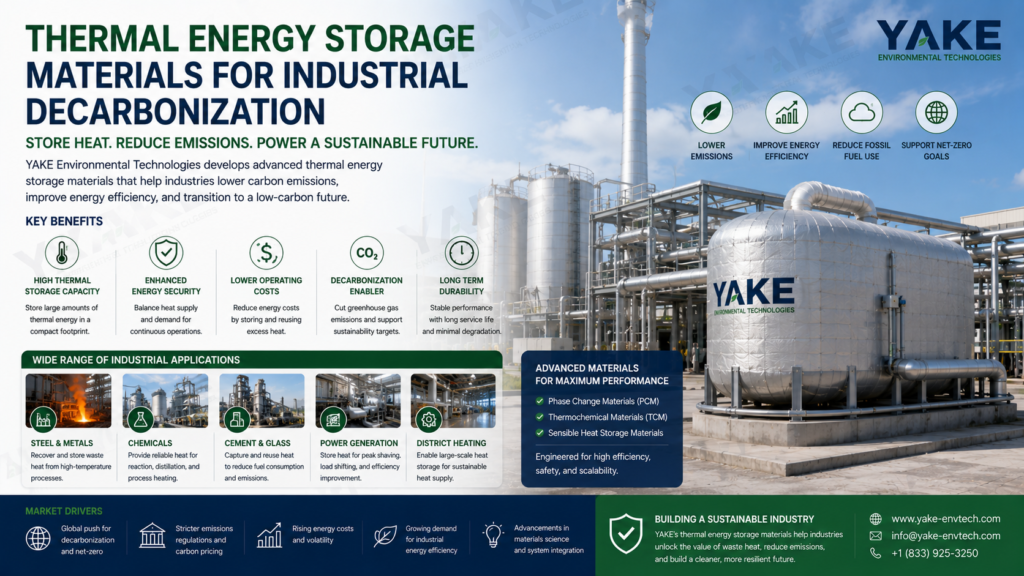

Thermal energy storage materials are materials that capture heat for use at a later time in heating, cooling, or energy systems. They often fall into three main types: sensible heat materials such as water or concrete, phase change materials like paraffin or salt hydrates, and thermochemical materials that use reversible chemical reactions. In industrial contexts, they assist in moving energy consumption away from peak periods, stabilize process temperatures, and increase overall system efficiency. Numerous plants utilize them with solar thermal fields, waste heat recovery lines, or chilled water systems to reduce energy costs and level output. The main body then dives into important material types, design considerations, and how they integrate into actual process layouts and control strategies.
Thermal energy storage materials are things that absorb heat, store that heat, and release that heat later as part of an energy system. They sit between the heat source and end use, so plants can move heat use across hours, days, or even seasons. At industrial sites, district heating, and grids with a lot of renewables, they increase efficiency, flatten peaks, and reduce fuel consumption. Three main groups matter in practice: sensible heat, latent heat, and thermochemical materials, along with newer hybrid concepts that blend these traits for better control and higher energy density.
Sensible heat storage increases the temperature of a solid or liquid but maintains it in the same phase. The energy stored scales with mass, specific heat, and temperature swing.
Water is the poster child. It’s cheap, safe, and boasts a high specific heat, but low volumetric energy density. Approximately 23 cubic meters of insulated water at a 70 °C temperature range is needed for just one moderate-size load. Tanks bulk up quickly in dense plants.
Molten salts, typically a combination of sodium nitrate, potassium nitrate, and calcium nitrate, are employed in solar thermal plants and high-temperature process heat. They operate at a few hundred degrees Celsius and align well with steam cycles. Solid media, such as rocks, sintered bauxite proppants tested up to 1,000 degrees Celsius, sand beds, and even “brick toaster” concepts that push solid blocks to 1,500 degrees Celsius, provide higher operating temperatures and simple construction.
Sensible storage is straightforward, cheap, and easy to scale. Its lower energy density results in larger footprints than alternatives.
Latent heat storage is based on phase change, usually solid-liquid. As it melts or freezes, the material stores or emits huge quantities of heat at a near-constant temperature, and that’s handy wherever strict temperature constraints apply.
PCMs are paraffin waxes, salt hydrates, and bio‑based blends. They can be embedded inside walls, tanks, or duct systems to even out temperature fluctuations. Ice is a well‑known PCM. A compact ice tank can cover cooling of a big building for a full day or more, letting chillers run at night when power is cheaper or cleaner.
PCMs provide greater energy density than sensible systems and can maintain setpoints very near a target temperature, which makes them ideal for cleanrooms, data centers, and certain drying or curing lines. They do suffer from issues like phase separation, sub-cooling, cycling fatigue, and good encapsulation and leak-tight housings being necessary.
Good system design must not only match PCM melting points to process needs but make sure heat exchangers can move heat in and out fast enough.
Thermochemical storage utilizes reversible chemical reactions to store energy in the changes of bonds instead of in temperature or phase only. Charging runs the endothermic reaction. Discharge runs the exothermic reverse reaction.
Some candidate materials include metal oxides, hydrated salts, and ammoniate systems. Since energy exists in chemical bonds, these materials can achieve very high energy densities and in principle store heat with very low standing losses over long periods, making them attractive for seasonal storage or constrained sites.
Challenges remain. Reaction rates can be slow, material stability and cycle life are not yet proven at scale, and reactor and balance-of-plant design is complex. Safely handling reactive solids and gases contributes constraints.
Still, thermochemical alternatives are being actively researched for high-temperature industrial clusters and dense long-duration storage paired with renewables.
Hybrid storage materials attempt to combine sensible, latent, and thermochemical characteristics into a single system. This includes composite PCMs with high-conductivity fillers, encapsulated PCMs embedded in concrete blocks, or packed beds that combine solid sensible media with small amounts of reactive or phase-change materials.
Research is driving composite shells, micro-capsules, and graded materials to boost energy density, reduce cycling degradation, and enhance thermal conductivity. Field pilots include sand-based thermal batteries, such as the Finnish unit that stores heat in a towering sand silo for district networks or ground heat exchangers that bank seasonal heat in soil or rock for building heating and cooling.
Thermal energy storage (TES) materials operate at multiple scales simultaneously. At the molecular level, they accumulate energy as sensible heat, which is the temperature increase in solids or liquids, or latent heat, which is the phase transition of salts, paraffins, or hydrated compounds. A few systems add thermochemical reactions, such as when water encounters a dehydrated salt and emits heat at about 50 °C in an exothermic reaction. At the mesoscale, you observe mass and heat transport through pores, channels, and packed beds, which determine actual charge and discharge rates. At the system scale, tanks, piping, heat exchangers, and controls determine how much of that stored energy you can really tap and how quickly.
Matching material behavior to the task is crucial. A molten salt loop at a solar plant, for example, could run between roughly 290 to 565 °C, whereas a low-temperature hot-water TES for HVAC applications might sit at somewhere between 40 to 90 °C. Other salts melt around 131 °C and can be pumped to 600 °C, air systems to 400 °C and sand or packed-bed units to around 500 to 600 °C using excess renewable power. Solid or molten silicon can get even higher, providing much greater energy density but stricter material and safety constraints. Over these alternatives, you select intelligent, hidden, or hybrid storage and then dimension residence time, storage time, and cycling profile. Insulation and thermal management materials surrounding the storage core reduce standby losses, defend structures and maintain safe external temperatures for personnel and adjacent equipment. Bad insulation will erase improvements from the best storage material.
Right material choice influences round-trip efficiency, corrosion risk, fire load, and maintenance windows. It directly impacts whole-system efficiency, safety, and service life. In industrial plants that already manage precise humidity and temperature with systems like Yakeclimate dehumidifiers, TES becomes one more thermal “asset” in the same control philosophy: predictable, stable, and built for long operating hours.
TES materials need to integrate into actual energy systems, not laboratory benches. In a plant loop, that means matching the temperature glide of the storage medium with real process demands and equipment constraints. Hot-water tanks for low-grade heat recovery from dryers or dehumidifiers might sit at 60 to 90 °C, while molten-salt or sand systems serving high-temperature process steam may need 400 to 600 °C. For district energy or industrial parks, the storage material has to match network supply and return temperatures so pumps, valves, and plate heat exchangers remain within design envelopes and water chemistry windows.
Heat exchangers are central to this integration. In a molten-salt arrangement, salt frequently serves as both a storage medium and a heat transfer fluid, circulating through tube banks that generate steam for turbines or process users. In air-based TES, hot air at temperatures up to 400 °C frequently passes heat into water or thermal oil through finned coils or packed-bed exchangers prior to its delivery to end users. Even plain water tanks for sensible storage depend on stratification and strategically located diffusers to preserve usable temperature layers. Control systems then schedule charge and discharge. They decide when to pull surplus electrical power, drive heaters or heat pumps, and when to send stored heat or cold to end uses like dryers, kilns, or air-handling units.
Control logic needs to consider source variability and demand spikes. A plant that already uses advanced controls for humidity and temperature can extend that logic to TES. It can add sensors for tank state of charge, salt temperature, or sand bed front position, then link this data to production schedules and tariffs.
Key integration challenges include:
Long‑duration and seasonal storage put much more rigorous demands on TES materials than short‑cycle daily buffering. Materials have to retain capacity and performance for thousands of cycles and long downtime periods. Thermochemical storage requires hydrated salts with stable hydration and dehydration behavior, with little phase segregation or crystal growth. In molten‑salt towers, the salt needs to be able to withstand decomposition and must not crystallize in pipes during cool spells. Sand and rock beds have to hold together and not sinter or settle in ways that clog flow pathways.
Key technical considerations are cycle life, degradation rate per cycle or per year, and the maintenance required to keep systems in spec. For a high-temperature molten-salt unit, operators monitor salt chemistry, oxidation state, and impurities that could increase the freezing point. Packed-bed systems depend on grain size distribution remaining within design limits so pressure drop and heat transfer remain constant. Even ‘simple’ hot-water tanks have liner fatigue, corrosion, sensor drift, and insulation aging. In all cases, the TES absorber and detector structure create a coupled system.
There are a number of strategies, including the most important, tracking long-term field data. Lab tests provide baseline stability, but real plants experience off-design operation, startup and shutdown stresses, and operator overrides. Logging outlet temperatures, state-of-charge, charge and discharge power, and unplanned outages over the course of years reveals real degradation and helps tune material selection or operational windows. Most plants already record granular data for air quality, humidity, and energy consumption. Including TES metrics in the same historian creates a complete image of plant thermal dynamics across seasons.
Long-term TES that’s robust helps stabilize wind- and solar-reliant grids. Excess mid-day power heats molten salt, sand, or silicon blocks, which then deliver steam or hot air for processing or district heat well after sunset. On the cold side, chilled water or ice storage can shift chiller loads and support low humidity cleanrooms when power is limited or costly. The more rugged the storage media, the greater trust operators and grid planners feel relying on TES as a steadfast asset.
Insulation and thermal management materials are frequently the determining factor in whether a TES system is even possible. Without good insulation, hot tanks for water, molten salt, sand, or silicon leak heat and lose financial worth. The same goes for cold storage like chilled water or ice tanks, or for liquid air where 700 liters of ambient air is compressed and cooled into approximately 1 liter of liquid. These high-density energy carriers require tight boil-off or heat gain management. Insulation reduces standby losses, controls surface temperatures to safe levels, and reduces the scale of heaters or chillers required to compensate for drift.
SPF is typical on mild-temperature tanks and piping since it offers the best thermal resistance per centimetre, sticks to awkward geometry, and can be sprayed on site. It is effective on hot-water TES or low-temperature chilled-water tanks, so long as UV and fire protection coatings are applied where necessary. Mineral wool, in board or blanket form, withstands much higher temperatures, making it a common choice for molten-salt tanks, hot air ducts up to roughly 400 °C, and sand or rock-bed housings. It provides excellent fire performance and retains mechanical strength as well. Reflective barriers like foil facings or multi-layer insulation (MLI) reduce radiative heat loss and are commonly found as an outer wrap or in cryogenic liquid-air systems.
For very high temperatures, such as solid or molten silicon or sand beds operating near 600 °C, engineers often stack several layers: refractory concrete or bricks inside, then high-temperature fiber blankets, then mineral wool or foam on the outside. Every layer experiences a different temperature band and deals with different stresses, from mechanical load to moisture or chemical exposure. For low-temperature cold storage that enables tight humidity control, vapor barriers are as critical as insulation because water penetration can ruin insulation and mess with dew points in air handling units.
Insulation choices best suited to different storage temperatures and environments include:
Thermal storage is at the heart of every ambitious strategy to decarbonize industrial heat. Heat represents a huge proportion of energy demand worldwide, and much of this remains fossil fuel-based. Storing this thermal energy for later reuse breaks this bond. It allows sites to extract energy when clean supply is abundant, store it in compact thermal media, then emit when heat or cooling is required instead of burning fuel on demand.
Thermal energy storage changes when and how you consume energy. A storage unit of fairly modest size can store sufficient energy to cool or heat a large building for a day or even a week. In district heating, molten salt or water tanks can store hundreds of megawatt-hours of heat, charged when electricity prices are low or when solar or wind output is high. One benchmark is that molten salt can deliver about 300 MWh with roughly 151,000 cubic feet of volume, while a comparable battery system may need about 800,000 cubic feet. That space gain counts in close-packed industrial parks and plugged-in urban plants.
This same logic scales in time, not just size. Thermal storage can be daily or seasonal, with storage holding energy for months or even years in underground pits, aquifers, or large insulated reservoirs. This assists in aligning summer solar surplus with winter heating demand. In process plants, thermal storage can capture waste heat from dryers, ovens, or kilns that would otherwise vent to air and feed it back into preheating, washing, or space conditioning.
Financially, it reduces fuel consumption, smooths peak demand and increases system efficiency. Plants can sidestep firing up gas boilers at peak tariffs, downsize grid connections and increase the capacity factor of both renewables and chillers. Research interest in thermal storage has increased over the last two decades, reflecting its growing importance in grids requiring flexible, low-cost storage. As renewables scale, these systems serve as a straightforward, robust buffer that is frequently less expensive per kilowatt-hour than electrochemical storage.
Thermal energy storage materials must be judged on clear, comparable criteria. For plant and facility teams, the useful ones combine high energy density, stable efficiency over thousands of cycles, acceptable cost per kilowatt-hour stored, and low environmental burden. Energy density and efficiency drive footprint and sizing. Cost and sustainability decide if a project ever leaves the design stage.
A regular test framework counts. Uniform charge–discharge cycles, HTF temperatures, and mass flow rates enable apples-to-apples comparison between salts, concrete, water, and PCMs. In practice, PCMs are typically evaluated in shell-and-tube rigs, each tube containing a specified PCM charge and subjected to controlled HTF conditions. Performance is subsequently monitored by means of liquid fraction, outlet temperature, and retained energy versus time.
A simple benchmark table helps teams screen options:
| Class / Example | Type | Main Strengths | Main Weaknesses |
|---|---|---|---|
| Water | Sensible | Very low cost, safe, widely available | Low energy density, freezing issues |
| Concrete / packed beds | Sensible | Robust, low cost, simple construction | Large volume, slower response |
| Nitrate molten salts | Sensible | Proven in CSP plants, good temperature range (≈300–600 °C) | Corrosive, needs high‑temp materials |
| Paraffin wax PCM | Latent | High latent heat, stable melt (≈55–57 °C) | Low thermal conductivity, often needs fins |
| Fatty acid PCM | Latent | Bio‑based, good latent heat (≈65–67 °C) | Cost, possible odor and stability concerns |
| Composite / nano‑PCM | Latent | Higher conductivity, tunable properties | Higher cost, more complex manufacturing |
Engineers have mixed paraffin wax and fatty acids to build a cascade across 55 to 67 degrees Celsius, matching low-grade heat recovery around HVAC or process cooling. Experiments then examine liquid fraction at various HTF temperatures and flow rates. For instance, at a fixed flow rate of 0.0119 kg per second, PCMs exhibit a brief low liquid fraction, whereas at 0.0277 kg per second, a liquid fraction of approximately 0.85 at 200 minutes for these materials suggests quicker charging but increased pump power consumption. For any of the materials, the practical measure is how effectively the system retains that stored energy with minimal losses for a sufficiently long period.
0.9, molten nitrate salts approximately 1.4 to 1.6. Greater numbers reduce tank weight for sensible units.
1.0 to 1.5, some salts higher. Low-conductivity PCMs typically require fins, metal foams, or graphite additives to maintain a decent power density.
Cost can’t end at material price per kg. Teams need to map total lifecycle cost, which includes procurement, system integration, civil work, insulation, pumps, sensors, and control hardware, plus maintenance and eventual replacement or recycling. A PCM in a shell‑and‑tube layout, for instance, could have a higher upfront cost than a bare water tank but could save on footprint and increase round‑trip efficiency.
With all technologies, it’s useful to weigh front cost against long term energy and production savings. More effective load shifting, more efficient utilization of low-tariff hours, and more stable chiller or boiler operation all translate to avoided peak demand charges and reduced mechanical wear. A solution with high energy density, good retention and tight control can allow downstream equipment — like dehumidifiers — to run at steadier setpoints and lower energy.
A cost-benefit matrix comes in handy. One axis enumerates technologies (water, concrete, salts, PCMs). The other lists use cases: HVAC cooling, low-grade waste heat, high-temperature process buffering. Each cell records capital cost per kWh, estimated savings, space requirements and control sophistication. For numerous others, economic feasibility emerges as the primary filter. If the payback period is too long, projects stall regardless of how strong the technical case might be.
Material selection is a third factor that defines the environmental footprint of thermal storage. Key criteria are resource abundance, mining or processing impacts, toxicity, recyclability and supply chain cleanliness. Water and concrete rate high in abundance but low in energy density. Others like molten salt rely on finite minerals and can be corrosive. Paraffin wax is typically fossil-derived, while fatty acid PCMs can come from bio-based streams, which could assist lifecycle emissions if they are well sourced.
Sustainable materials assist in reducing storage systems’ carbon footprint by minimizing embodied energy and simplifying end-of-life processing. A PCM that retains performance over multiple cycles and can be recovered or recycled minimizes waste quantities and disposal hazards. When thermal storage is combined with effective humidity control, chilled-water loops, or heat recovery to regenerate industrial dehumidifiers, these savings ripple through the entire plant energy balance.
Relevant certifications and standards include:
Scaling thermal energy storage from pilots to grid and plant scale is where most ideas stall. Small tanks and test rigs do the trick. Multi-megawatt systems that run day and night next to actual lines and actual ovens are different.
Here’s the crux. Large sites require a massive increase in storage capacity, typically from a few MWh in pilot trials to hundreds MWh in full service. That drives cost, space, and risk. Material volumes rise fast: more salt, concrete, steel, insulation, and control hardware. Unit prices might come down with volume, but total capital cost still scales, as does the cost of civil works and safety systems. For a plant manager, this is concrete. It’s a new asset that needs to compete with fuel, batteries, and process upgrades on a rigid payback.
Technical constraints emerge early. As tanks become larger, heat transfer rates decrease unless the design changes. Long paths imply strong thermal gradients, mixed flow and dead zones. Fluid dynamics in big tanks or packed beds are harder to predict and harder to fix once built. Materials are exposed to increased strain from thermal cycling, corrosion and mechanical load. Phase-change materials help by packing more energy per cubic meter than sensible heat media, but they add their own needs: stable melting ranges, good conductivity, safe containment and long-term cycling data.
On the grid side, system integration is another barrier. Large thermal storage must align with variable renewables, plant loads and district networks without overcomplicating controls. It needs to be compatible with existing boilers, chillers or heat pumps and still permit transparent metering and servicing. It needs to be designed in a way that is modular enough that engineers can add or swap units, like we do with modular dehumidifiers in multi-line production halls. Standard interfaces, repeatable module sizes and a stable supply chain for media and hardware minimize risk and facilitate global rollout.
Future thermal storage will depend on improved materials and intelligent system design that meet real plant limitations on cost, footprint, and reliability. The direction is clear: higher energy density, higher working temperature, tighter coupling with renewables, and easier integration into existing process lines and district networks.
Materials science is advancing quickly in both sensible and latent heat storage. New ceramic and concrete composites, often with embedded metal oxides, now cycle thousands of times with little degradation and at costs already below lithium-ion per kilowatt-hour of stored heat. For latent storage, next-generation phase-change materials employ customized organic-inorganic mixtures and encapsulation to minimize supercooling, minimize leakage, and provide more consistent melt-freeze temperatures. Molten salt research is evolving past traditional nitrate mixtures, toward stable molten hydroxide and chloride mixtures that raise operating temperatures beyond 600 to 700 degrees Celsius. One of the first was a 1 megawatt / 20 megawatt-hour molten-hydroxide system, demonstrating how compact and cost-driven these high-temperature tanks could be in an industrial yard.
AI-driven design is starting to transform how these materials are discovered and scaled. Rather than trial-and-error lab work, models now screen thousands of salt, ceramic, or composite formulations against melting point, thermal conductivity, corrosion with steels, and cost. The same tools can co-optimize material and system. For example, they can match a thermochemical pair to a specific kiln line that runs at 450 °C or tune storage for a Stirling or reversed Brayton cycle block. This is one reason Stirling engines, augmented thermoelectrics, and thermo-photovoltaic cells are back in play as more stable high-temperature media render these conversion systems more efficient and easier to maintain.
On the grid and district side, large thermal storage is getting increasingly tied closer to solar and heat networks. Tanks, aquifer thermal energy storage, and shallow geothermal wells are now common in district heating and cooling in Europe, Asia, and the Middle East, where seasonal storage helps ride out swings in demand. Thermal systems can absorb extra solar output during the day and discharge it at night, bridging the generation-load divide without massive electrochemical banks. Concentrated solar power falls in line, with hotter molten salts and ceramic receivers powering next-generation Brayton cycles. For these hard-to-electrify sectors requiring 300 to 400 degrees Celsius and above—metals, ceramics, chemicals, cement—thermochemical storage is gaining attention because it delivers more energy density and better cyclability than sensible or latent heat alone, and it can integrate into existing high-temperature process arrangements.
Thermal energy storage materials are now the centerpiece of intelligent heat consumption. They shave peaks, reduce fuel burn and bridge solar and waste heat gaps. Plant crews score real victories here. There is a shorter ramp to times. There are consistent outlet temperatures. There is less stress on boilers and chillers.
Nice selections require transparent mathematics and transparent objectives. Thermal energy storage materials 2.0: 1. Match the phase change point to your process. Verify cycle life, safety, and cost at scale. Test actual flow, actual fouling, and actual start‑stop cycles. Think of the tank, heat exchangers, and control logic as a system, not loose components.
For your next upgrade or line change, get thermal storage into the design first draft and not the last!
Thermal energy storage materials capture, store and release heat for subsequent use. They assist in equalizing energy supply and demand. Typical examples are water, molten salts, PCMs, rocks, and cutting edge ceramics in industry and construction.
They store heat when it is present and release it when it is required. They utilize sensible heat (temperature change), latent heat (phase change), or thermochemical reactions, which makes the entire system more efficient and facilitates renewable energy embraces.
They address the temporal disconnect between renewable energy generation and consumption. Stored heat can then be used hours or days later. This bolsters reliability, cuts fossil fuel dependence, and enables stable grid operation with solar and wind.
Phase change materials absorb and release considerable amounts of energy when they melt and solidify. They operate at almost isothermal conditions. PCMs can be used in buildings, cold chains, electronics cooling, and industrial systems to enhance comfort, efficiency, and temperature stability.
The most important factors are energy density, operating temperature range, thermal conductivity, cycle life, cost, and safety. Chemical stability, corrosion, and compatibility with system components are considered by engineers. A good material finds that sweet spot between outstanding performance, practical deployment, and long-term reliability.
Scaling demands cheap materials, long-lasting systems, and easy manufacturing. Many of the top performing materials work in labs but are costly or hard to manufacture at scale. Compatibility with current infrastructure and safety standards is another significant challenge.
Research includes advanced PCMs, high-temperature ceramics, hybrid systems, and thermochemical materials. There’s strong interest in recyclable, low-toxicity, and bio-based materials. These innovations seek to boost energy density, reduce cost, and enable mass renewable energy penetration.
Contact us to find the best place to buy your Yakeclimate solution today!
Our experts have proven solutions to keep your humidity levels in check while keeping your energy costs low.


