
A closed growing room still needs a defined water and energy balance. Fresh-water consumption, crop evaporation and water removed by climate equipment describe different flows. Treating them as interchangeable can distort both equipment sizing and a proposed water-recovery benefit.
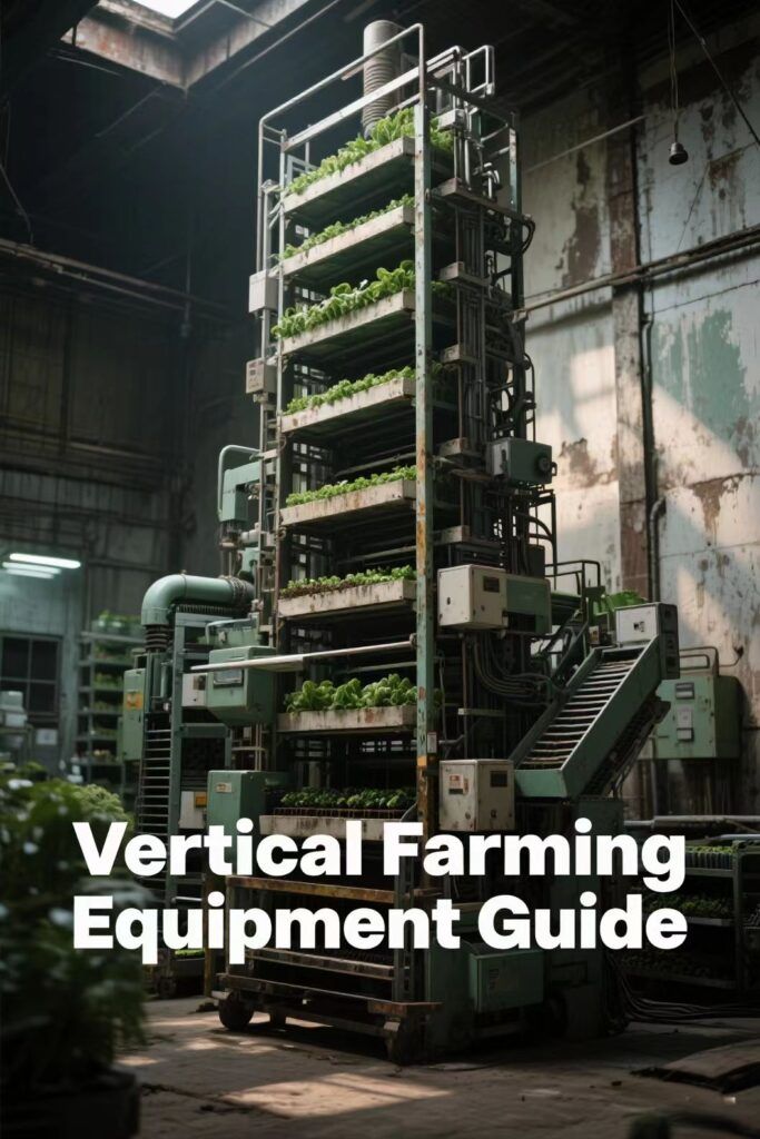
Illustrative growing-rack arrangement.
Draw the boundary before reading the water meter
Start with a diagram of the room, nutrient tanks, drains, cooling coils and any condensate return. Mark every flow that crosses the boundary you are analysing. A recirculating flow cancels from the balance only when both ends lie inside that boundary.
For the growing system, account for irrigation entering, drainage leaving, changes in stored water, water retained in the crop and evaporation to the room. A difference between irrigation and drainage is not automatically leaf transpiration: storage changes and evaporation from other wet surfaces may also contribute.
For the entire facility, recovered condensate returned to irrigation is an internal transfer. It can reduce outside make-up water while water continues moving from crop to air and back through the climate equipment. The facility supply meter consequently cannot, by itself, measure the circulating moisture load.
| Boundary | Useful records | Interpretation to avoid |
| Root zone and irrigation | Supplied water, return drainage and storage changes | Every unreturned litre was transpired immediately |
| Growing-room air | Moisture sources, equipment removal, air exchange and changing air moisture | Every litre entering the room was removed by one dehumidifier |
| Whole facility | External make-up, discharge, harvest and storage changes | Low make-up water proves a low internal moisture load |
If a room has negligible moisture exchange with outside air and its moisture content is stable, its removal routes must balance its moisture sources. Record whether those routes are cooling coils, dedicated equipment or something else. Uncontrolled condensation on a building surface should not be counted as satisfactory climate control. The moisture-load definition helps keep the quantities consistent.
A daily total does not reveal the hourly peak
Consider a hypothetical measured evaporation total of 4,000 litres in one day. The following calculations illustrate time allocation; they are not crop design values.
| Assumption | Calculation | Result |
| Average over the full day | 4,000 L ÷ 24 h | 166.7 L/h |
| All evaporation assigned to 18 lit hours | 4,000 L ÷ 18 h | 222.2 L/h during that assumed period |
| An illustrative 80% in 18 lit hours | 3,200 L ÷ 18 h | 177.8 L/h during the lit period |
| Remaining 20% in six dark hours | 800 L ÷ 6 h | 133.3 L/h during the dark period |
None of these averages establishes the maximum hourly duty. Measure or model the time profile, including dark operation, instead of assigning the whole daily total to the photoperiod by assumption.
Graamans and colleagues' 2017 lettuce study modelled sensible and latent exchange in closed production. Its validation considered light level, cultivation-area cover and air humidity. Those are defined study inputs, not evidence that every crop's transpiration rises in fixed proportion to lighting. Revisit the load record when the crop, planting arrangement or operating schedule changes. See plant transpiration and latent load for the terminology.
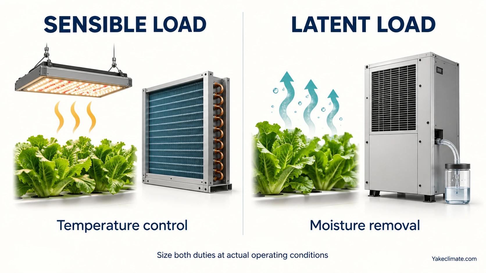
Separate duties can be served by integrated or separate equipment.
Evaluate cooling and dehumidification together
Distinguishing sensible and latent duties does not require separate machines. In Blom and colleagues' 2023 modelling study, the baseline vertical farm used an integrated water-to-water heat pump with cooling below dew point, reheating and rejection of excess heat. This was a selected research configuration, not a Yake installation or a guarantee for other systems.
For a proposal, request a schedule showing temperature control and water removal at the same operating points. Include where recovered or rejected heat goes and how the controls respond when the two duties change. The temperature and humidity control explainer provides the wider context.
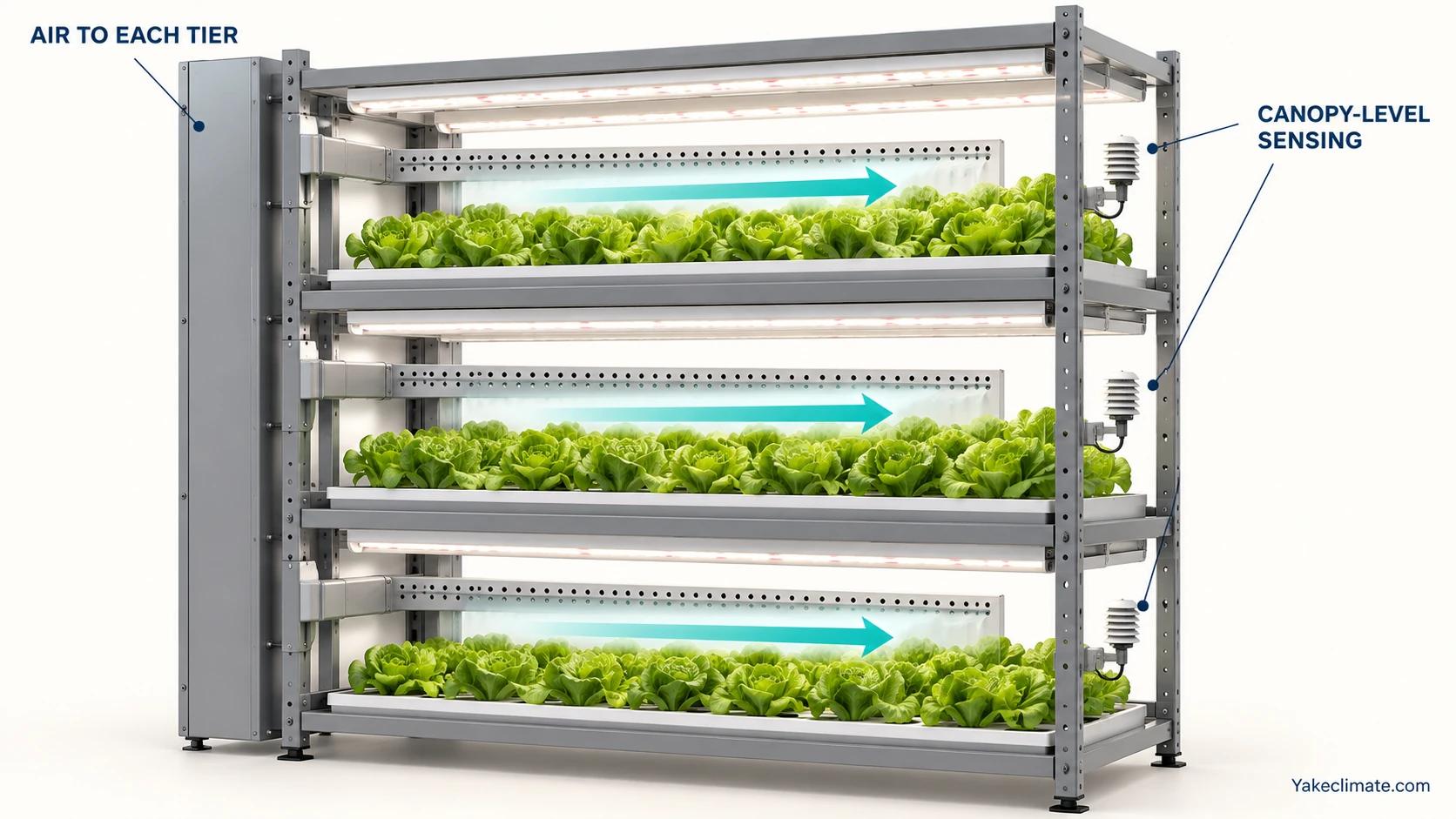
An illustrative layout for discussing tier-level observations, not an installation specification.
Investigate tier differences without assuming the cause
Compare representative crop locations with the room control sensor on the same timeline. Record temperature, humidity, equipment state and visible condensation; identify each sensor and its position. An upper/lower difference is a finding to investigate, not proof that either airflow or installed capacity is the sole problem.
The illustrated branches and sensors show one way to organise observations. They are not a universal duct layout. Review distribution, available duty, control behaviour and measurement quality together before requesting additional equipment.
Treat condensate as a managed water stream
An EPA study summary of condensate from 13 air handlers at four locations reports microbial and metal-related water-quality concerns. Those building systems are not a validation of hydroponic reuse. Clear appearance or condensation alone cannot establish suitability for a crop-water circuit.
Record the collection route, intended use, storage and treatment proposal, then obtain the project's water-quality assessment. Meter recovered water separately from outside make-up so that reuse is visible in the facility balance without disappearing from the internal climate duty.
Prepare the equipment and operating brief
Include crop and lighting schedules, measured load profiles, room and tier observations, drainage routes, heat interfaces and service access. State what operators should see when a unit stops or conditions are missed, who responds and which contingency is available. Redundancy should follow that project assessment; a particular equipment count is not established by this article.
Compare ventilation and dehumidification where outside-air exchange is part of the design. Our agriculture and ceiling dehumidifier pages describe the equipment context. The RYDZ-12S product page lists 288 L/24h at 30°C and 80% RH, 3,000 m³/h airflow and an applicable temperature range of 5–38°C. The capacity rating belongs to the stated test condition, not every point in that temperature range. Submit the operating brief through project contact.
