
Building 34, No. 535 Shunfeng Road, Hangzhou, Zhejiang, China
[email protected]
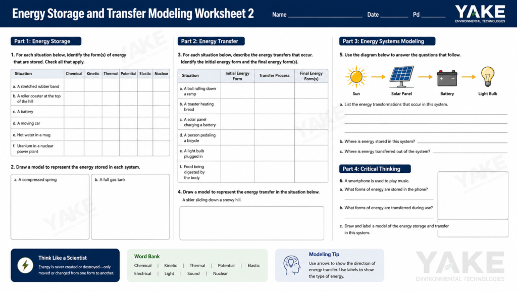

Energy storage and transfer modeling worksheet 2 is a structured tool that helps map how energy moves and changes form in a system. It frequently dissects a process into steps, monitors inputs and outputs, and employs explicit iconography to indicate when energy is stored, transferred, or wasted. Like many worksheets of its type, it connects to hot load, electrical storage, or work and supports simple and multi-stage systems. In industrial work, the same logic applies when modeling heat recovery loops, battery-based backup, or compressed air networks. The content therein explains how such a worksheet cultivates stronger insight, eliminates conjecture, and establishes a foundation for more precise energy management and planning.
Energy storage and transfer are at the heart of all physics and engineering models. In worksheet 2, every number you plug in and every diagram you draw hinges on these fundamentals. An intuitive understanding of what energy is, how it flows, and where it resides in a system underpins any reliable energy storage and transfer model, be you sizing a battery bank, auditing a drying oven, or optimizing an industrial dehumidifier line.
The principle of conservation of energy states energy can neither be created nor destroyed, only transformed from one form to another or exchanged between a system and its environment. In a closed system, the overall amount of energy remains constant with time even as kinetic, potential, thermal, or electrical fractions increase or decrease.
This law is the foundation of every serious energy modeling spreadsheet. For each step in worksheet 2, energy in total energy out plus change in stored energy. If you catch energy “popping” in or out in your figures, it’s almost always a missing term, wrong boundary, or unit error.
Apply conservation as an internal audit. After every major step, add up all energy forms and transfers and verify that the totals agree within a reasonable margin. This habit is the same reasoning as balancing an industrial heat and mass model for a dehumidification train.
In most industrial problems, you will track at least these forms:
Figure out which ones count before you mess with the figures. Gravitational potential energy, for example, relies on the height of an object above a reference point, while elastic potential energy may reside in a spring or flexible seal. Kinetic energy propagates through impacts or convective structures, like high-speed air currents powering fluid droplets or particles of dust.
A simple table keeps this organized:
| Energy form | Where it is | How it changes |
|---|---|---|
| Kinetic | Air stream | Fan speed, duct losses |
| Thermal | Process air | Heaters, coils, dehumidifier load |
Place such tables next to bar graphs to indicate how each type transforms to other types along your worksheet trails.
Energy moves through a system by a few main mechanisms: conduction, convection, radiation, and work. Conduction addresses heat through solid walls or coil tubes. Convection covers energy transported by moving fluids. Radiation covers high-temperature or exposed surfaces. Work connects to shafts, pistons, fans, and compressors.
Trace these paths with an immediate block diagram of your system and environment. Box up air spaces, coils, walls, products, arrows for conduction through metal, convection in air, radiation from hot surfaces, and mechanical work in drives. Describe each arrow with the mechanism and, if known, the rate.
On the worksheet, maintain that same clarity. Label each transfer step with its mechanism, for example, “convective heat gain to air,” “shaft work to fan,” or “radiant loss to roof.” This explicit tagging keeps your overall energy accounting straight and makes subsequent audits much quicker, particularly when you compare the model to measured plant data.
This worksheet is best when you proceed sequentially, step by step. Each block feeds the next, so a small error early can skew every subsequent outcome. Treat it like a process sheet on the line: follow the sequence, log the data, and double-check as you go.
A simple checklist helps:
Begin by sketching obvious system boundaries. State what physical space and which assets sit inside the model. For example, an industrial dryer chamber, the air in it, the product on trays, and any heating coils or dehumidifiers.
Pay attention to what you leave out and record it. Maybe you exclude building walls, upstream steam lines, or the chiller plant. That selection has to be apparent so the rest of us know how to interpret the digits.
Create a rough sketch. Show boxes for subsystems (air zone, product, coil, dehumidifier) and arrows for energy flows: electrical input, hot water loop, latent heat removed by the dehumidifier. Then enumerate all of the objects and interactions beneath the diagram in a brief bullet list so no element of the system remains ‘in your head only.’
Log all starting conditions in one table: air temperature (°C), humidity ratio (kg/kg dry air), product mass (kg), product moisture content (%), coil surface temperature (°C), fan power (kW), and dehumidifier capacity (kW or kg/h water removal).
Incorporate measured values wherever possible. If you have to guess, note the origin and way, for example, psychrometric chart or previous batch data. The fidelity of this block determines the upper bound on the quality of the overall model, so stop and sanity check each entry.
List each way energy can move: convection from air to product, phase change during drying, electrical input to heaters and fans, latent removal in the dehumidifier, and losses to surroundings through panels or ductwork.
List the unwanted paths, such as leakage to an adjacent room, bypass air around a heat exchanger, or condensation on cold ducting. They frequently account for discrepancies between model and meter readings.
A quick scratch with arrows and labels usually reveals missed paths. Go through the list. Missing even a rough loss channel, a sizable one, is still missing.
After you simulate or measure the run, fill in the same table format for the final state: new air conditions, updated product moisture, coil temperatures, and any logged energy use from meters in kilowatt-hours.
Compare initial and final tables side by side. Verify that total energy in equals total energy stored plus losses within a reasonable tolerance. Update your diagram if new transfer paths emerged in practice. Highlight any gaps that look too big to overlook.
To interpret a storage and transfer model is to interpret the flow of energy, its sources, its effects, and its transformation within a defined system boundary. Sketch that boundary with a dotted line initially, so you understand what is “inside” the system and what is “surrounding” it, be it a paint line oven, battery dry room, or climate controlled warehouse. Then read the numbers and diagrams for patterns, not just single values, and always compare what you see with basic physical rules: energy is conserved, losses show up as less useful output, and any “extra” energy must be accounted for as heat, friction, or other side paths.
Notice how each component connects to the subsequent one, as interpreting your model is really about the connections between components, not the components in isolation. Check energy input, storage, transfer, and loss in sequence, and ask the three core energy questions at every step: where does the energy come from, what does it do, and how does it change on the way out. Simple tools assist here; even a quick pie chart of input versus output forms or latent versus sensible heat in an air-handling system can provide a rapid qualitative perspective on what dominates the balance. When the worksheet addresses humidity control, you can immediately observe the amount of electrical input that converts to productive moisture removal and the amount that wafts out as waste heat in the space.
When interpreting your model, look at the outputs for patterns and outliers, not just means. If energy use spikes when ambient humidity rises, that pattern says your system is sensitive to external moisture load and could use a more efficient dehumidifier or better zoning. If your model says you are getting more useful energy out than you put in, that is a red flag for a setup or unit mistake, not a miracle device.
Treat efficiency in the worksheet as a clean ratio: useful energy output divided by total energy input, using joules in and joules out where you can. For a dehumidification train, useful output could be latent heat extracted or kilograms of water condensed, and input is the electrical power into compressors, fans, and controls during the same period. Write it as η equals productive output divided by all input. Put efficiency as a percentage to make cross-comparisons easy across lines or plants, for example, electrical-to-dry-air delivery for dry room versus paint booth. Then build a simple table that lists every loss term found in the model: casing heat leak, fan pressure drop, regeneration coil overshoot, standby power in drives, or reheat that adds no extra moisture control. Treat those metrics as a design and operations manual, not just a report. Low subsystem efficiency ought to highlight solid options like higher-grade insulation, better heat recovery, or a switch to higher COP industrial dehumidifier where it suits the duty cycle.
All real systems have losses and the worksheet ought to reveal them. For storing and moving energy, typical ones include heat loss through walls and ducts, friction in fans and blowers, electrical resistance in heaters and drives, and nonideal heat exchange between process air and coils.
Count each one wherever the data permits. That could be watts of motor copper losses, kilojoules of heat bleeding out a duct an hour, or pressure drop turned into heat across a filter bank at a flow rate. When values are coarse, document the assumptions, but leave the numbers in clear view.
Build a short checklist to lock this down:
Static snapshots can conceal much. In typical industrial facilities, energy flows drift with shifting loads, weather, and production schedules, so interpret the model accordingly. A drying tunnel at 08:00 with cool, dry intake air does not behave like the same tunnel at 16:00 in hot, humid conditions. Your worksheet should capture that change if it includes time steps or scenario runs.
Consider fluctuating load, ambient temperature, and humidity dynamic drivers. For instance, increasing outdoor humidity spikes latent load on your coils and dehumidifiers, and your model should reflect that as greater input energy for the same product output. If your worksheet allows, plot key variables against time: input power, stored thermal energy, moisture content, and outlet conditions. These time plots simplify observing start-up transients, ramp-up phases, and steady-state plateaus.
Be on the lookout for feedback loops or time-lag effects. An overheated equipment room may warm intake air to a desiccant unit, which runs harder, dumping even more heat back into the same room. The model might reveal a slow creep upward in room temperature and energy consumption over a matter of hours. When you encounter that sort of loop in your data, highlight it. The solution could be as straightforward as local ventilation or as intricate as an air path redesign, frequently combined with higher-efficiency Yakeclimate units that accomplish the same duty with less waste heat and reduced input power.
Energy storage and transfer modeling worksheet 2 has value only if the assumptions are transparent, forthright, and connected to plant reality. Every section of the worksheet should require users to record each assumption, describe why they made it, and identify whether it is a hard constraint from physics, a pragmatic shortcut, or a shaky assumption. That clarity transforms the worksheet into something you can rely on to size storage tanks, set dehumidifier loads, or check peak power draw for air-handling units.
Best-case scenarios are the traditional hacks that make the math nice and neat. In energy storage and transfer work, that often means things like no heat loss to ambient air, constant specific heat capacity, uniform air temperature in a duct, dry air with no phase change, perfectly mixed tanks, no thermal bridges at duct joints, or “steady state” operation of a dehumidifier coil. The worksheet should call these out by name, not hide them behind symbols.
Users should mark, for each step, where such idealizations enter the calculation: for example, “Section 2.1: assume adiabatic walls on air distribution plenum” or “Step 4: neglect fan heat gain in latent load balance.” Diagrams and tables require visual flags as well, whether it be a column entitled “Idealized?” or a brief annotation on the sketch in proximity to important pieces.
The intent and boundaries of each idealization should be described in lay terms. For example, assume no heat loss to ambient to simplify tank sizing. This is true only for short-term discharge of less than 10 minutes and good insulation of 0.2 W/m²·K or less. That sort of caveat helps a facility engineer know when the output is sufficient for first-pass dehumidifier sizing and when they need a more precise model.
Real systems act in messy ways that models gloss over. Those gaps are significant for moisture management. Air leaks around doors, imperfect duct insulation, part-load cycling of compressors, sensor drift, frost on coils, and non-uniform air flow across a heat exchanger all alter real energy storage and transfer. The worksheet should encourage them to detail these gaps for each perfect condition.
Engineers should record observed or expected deviations. For example, “Measured supply air 2 to 3 degrees Celsius warmer than model at line A during peak shift,” or “Condensate carryover seen at high latent loads, not represented in model.” Even a rough note such as “fan power plus or minus 10 percent from nameplate” is better than silence.
Where data do exist, users should attempt to measure the influence of these voids. That might mean comparing BMS trend logs with model outputs, applying simple correction factors, or running quick sensitivity checks. If duct loss is 5 percent versus 0 percent, coil duty rises by 8 percent.” These figures assist in indicating if a normal Yakeclimate dehumidifier model suffices or if you require a special configuration or control scheduling.
To close the gaps, the worksheet can recommend practical actions like improved insulation on chilled lines, sealing identified leakage pathways, adding or re-calibrating temperature and RH sensors, or updating equipment curves with site-specific performance tests. This connects modeling efforts to daily optimization of energy consumption and process robustness.
Each assumption and hole shifts how much you can trust the output. The worksheet should contain a brief ‘assumption impact’ block following each key result, prompting the user to qualitatively rate sensitivity (low/medium/high) and, where feasible, pair a numerical margin of error. For example, ‘Storage tank heat loss neglect adds 3 to 5 percent error over 1 hour’ or ‘Ignoring coil fouling likely underestimates dehumidifier power by up to 10 percent after 1 year.’
Users should remark on reliability for particular decisions. It may be ‘sufficient for comparing two control strategies’ but ‘not sufficient for final motor sizing or contract guarantees.’ That distinction prevents stakeholders from over-exploiting a quick worksheet as if it were a full CFD or dynamic simulation.
The same section should collect ideas for the next modeling round: add transient behavior for start-up, include moisture sorption in walls, or separate sensible and latent heat with more accurate psychrometric data. Over time, this creates a history of how accurately the worksheet predicts actual plant performance and where the heuristic model for energy storage and transfer in air handling and dehumidification should become more nuanced.
Energy storage and transfer modeling worksheet 2 generates value when the math matches real systems. Bridging theory and reality here means taking the abstract physics tools—W, Q, and R energy transfer mechanisms, Ek, Eg, Eel storage terms, and the First Law—to say what your line really does under load, not what it does in an ideal textbook world.
Anything in the worksheet needs to correspond to something you can quantify or find a source for. Cross-check every crucial input against plant historians, calibrated sensors, lab tests, or peer-reviewed sources. For instance, if you take air at 30 °C and 80% relative humidity upstream of a dehumidifier, verify that with recorded measurements, not recollection.
Flag any data point that looks off: jumps in temperature, odd mass flow rates, unrealistic specific humidity, or compressor power that does not fit nameplate and measured amperage. Take quick marks in the sheet, comments, and color codes.
Update entries when you detect drift or poor baselines. Swap out rule-of-thumb k-values with values from recent commissioning tests. Update energy transfer terms (W, Q, R) so the First Law balance closes for each closed system you define. Maintain a brief validation log that records source, date, method, and correction factor if any so audits and future engineers know why a number can be trusted.
Visual verifications assist. Energy conservation bar graph diagrams (LOL charts) adjacent to the numeric table can expose when Ek, Eg, and Eel do not sum with the work and heat terms you assert.
Use the worksheet as a living model, not a one-off file. Do cycles of ‘model → test → adjust’ anytime process conditions change, equipment is upgraded or control schemes shift. Each time you compare predicted coil load to measured kW on a Yakeclimate dehumid, tweak the heat transfer or fan power terms if the gap is systematic.
Document each polish directly on the worksheet. Tag with version, date, what you changed and which outputs shifted. Follow updates to see how they affect peak load, part-load behavior, and anticipated energy consumption per kg dry air. Set clear stop rules. For example, “Model is acceptable when energy balance closes within ±3% for three independent test days” or “Predicted latent load is within ±5% of logged data over a full season.” This saves you from infinite fiddling, yet still respects real-world dynamics.
A helpful model doesn’t just explain historical data. It predicts what will occur when you adjust set points, air flow, or product load. Verify it by applying the worksheet to forecast performance in novel situations and comparing the results with new field data, such as a different season or production shift. Use formulations like Eel equals 0.5 k x squared when you model elastic elements alone, but always contextualize them in an obvious closed system so total energy is still conserved.
Or, map the edges. Note where the model fails: extreme humidity spikes, startup transients, or non-steady states with rapid W, Q, and R swings. Record both accurate and inaccurate forecasts along with the circumstances. This establishes a collective vocabulary and renders theoretical ideas concrete enough that groups can rely on the framework with explicit trust and implicit constraints.
Worksheet Review Sheet Solutions for ‘Energy Storage and Transfer Modeling Worksheet 2’ work best when they help you visualize direct connections between theory, numerics, and plant reality. They are not just to get the answer, but to see how the method would translate in a real assembly line, drying room, or paint booth.
Begin with solutions to each common problem type. For a simple thermal energy storage task, the sheet should spell out: identify the system boundary, write the energy balance, choose the right form of the storage equation. For example, Q equals m times c sub p times delta T for sensible heat, plug in units in SI, then solve and sanity-check against expected ranges. For transfer questions, it should go through how to separate conduction, convection, and phase-change terms, which is crucial when you size coils or dehumidifiers in a high-humidity process space. A lot of powerful sheets utilize a combination of short answer solutions and complete worked examples, so the reader experiences both quick checks and deep dives.
They would then check their worksheet answers against the solutions as a way of self review. It’s typical at schools, but it works nicely in-house for operators and junior engineers. A good sheet lets them line up each step, not just the final joules or watts, with the model method. Some solutions include a brief “real-world” note, for example, how that very same storage model translates to a buffer tank in a low-temp drying loop or a desiccant wheel energy balance.
Once you’ve done the comparison, it aids in dissecting errors. Identify whether the mistake originated from unit slips, incorrect property data, or a bad choice of control volume. That sort of review prevents teams from recreating the same modeling gaps when they design new humidity controls or benchmark loads prior to installing a Yakeclimate dehumidifier.
Finally, make a small cheat sheet of review sheet takeaways. Summarize patterns: which equations matter most, which assumptions are safe, and where you need better data. That list turns into an easy design checklist when you are pressed for time on the plant floor.
Energy storage and transfer modeling appears easy on paper, yet it defines actual equipment, actual routes, actual danger. The worksheet isn’t a school exercise. It trains lucid thinking. It makes each step in the flow of energy pay its own way.
You observed how every sketch, every table and every number corresponds to an actual component, an actual loss or an actual safety limit. You got a glimpse of how model assumptions can skew outcomes and how validations with actual data keep the work grounded.
Next, take this worksheet into your plant or lab on a live process. Run it, test it, tweak it, run it again, and let it direct the next round of fixes and upgrades.
This worksheet guides you to model energy storage, transfer, and conservation in actual systems. It expands on foundational energy concepts and takes you step by step to develop lucid, quantitative models.
No. All you really have to know is a little bit about energy (kinetic, potential, thermal) and some simple equations. It’s a learner worksheet with prompts and examples.
It requires that you define systems and energy pathways and employ diagrams and equations. By modeling each step, you observe precisely where energy is transferred and how much is transferred or transformed.
Assumptions specify what you include or exclude in your model. They enable calculability but constrain precision. The worksheet trains you to articulate, interrogate, and polish these assumptions.
Use your model outputs with real or reference data. Verify conservation of energy and that values are reasonable. These are guided by the “Interpreting Your Model” and “Bridging Theory and Reality” sections.
The solutions contain example answers, complete calculations, and explanations. They emphasize typical errors and superior options, allowing you to self-audit your efforts and become a better modeler.
Yes. These modeling steps dovetail nicely with lab investigations and project work. You can use the same frame to plan experiments, analyze findings, and explain energy flows clearly.


Contact us to find the best place to buy your Yakeclimate solution today!
Our experts have proven solutions to keep your humidity levels in check while keeping your energy costs low.