
Building 34, No. 535 Shunfeng Road, Hangzhou, Zhejiang, China
[email protected]
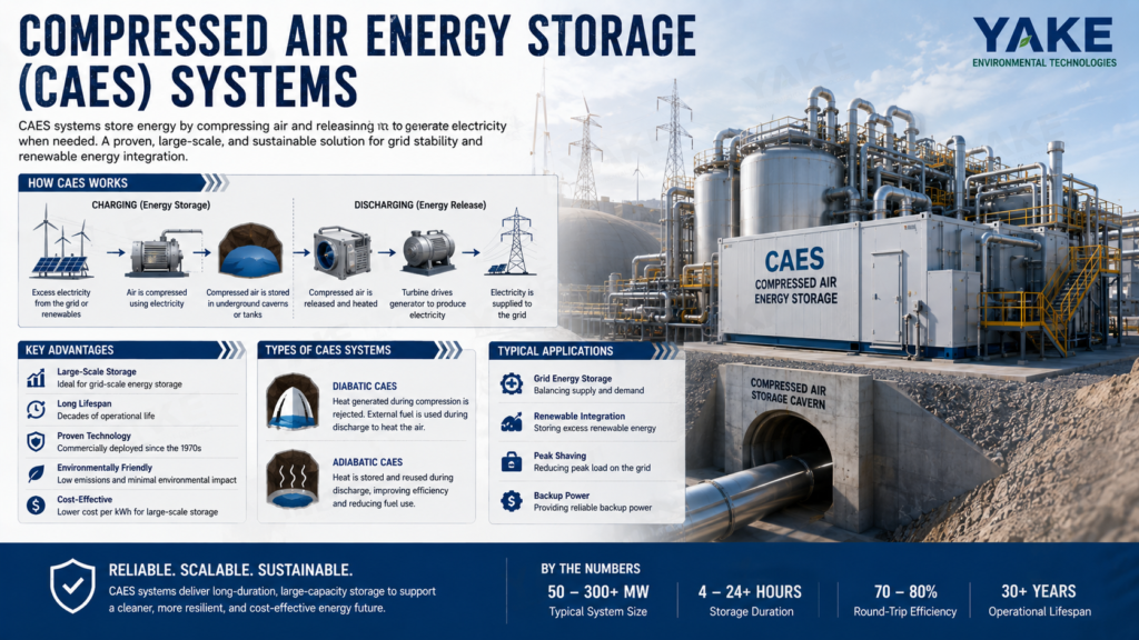

CAES energy storage systems are large-scale setups that store energy by compressing air in underground caverns or pressure vessels and later release it to drive turbines for power generation. They frequently pair with wind or solar plants to level output, bolster grid stability and offset peak demand. In many projects, CAES serves as long-duration storage, ranging from several hours to full-day cycles, where batteries become less economical. Contemporary designs employ enhanced heat recovery, improved seals and control systems to increase round-trip efficiency and reduce emissions. In industrial areas, CAES can back local microgrids and critical loads. The following sections explore design decisions, applications and engineering constraints for actual projects.
CAES captures excess electrical energy by compressing air, then uses it later to spin turbines and return power to the grid. For industrial users, this converts variable renewable supply into firm capacity that can sustain stable plant loads, HVAC, and huge dehumidification machines.
In the charge phase, electric motor–driven compressors consume excess grid power, typically during off-peak hours or from surplus wind and solar, to pressurize ambient air. Multi-stage compressors with intercooling pressurize air to very high pressures, sometimes tens to hundreds of bar, with utility-scale storage connected to caverns rated in excess of 10 MPa.
Heat loss in this step is the key technical sore. Ideally, adiabatic compression would retain all that heat and approach near-100% theoretical efficiency, but real systems dissipate heat, and round-trip efficiency hovers closer to 70%. The compression train by itself can achieve approximately 82% efficiency when well designed and well maintained.
Advanced adiabatic CAES attempts to capture this heat in separate thermal stores, occasionally achieving thermal efficiencies exceeding 96% in prototype experiments. Heat can bake in concrete or packed stone, or in fluids such as hot oil to around 300 °C or molten salt close to 600 °C, waiting to be recycled during the expansion phase. Since compression power is frequently the largest single operating expense, an improvement at this stage shifts the needle for total project economics.
Once compressed, air is directed to storage capable of long duration and high pressure. Large plants typically utilize underground salt caverns, aquifers, or depleted gas fields, where rock integrity and low permeability maintain minimal losses over years.
Surface vessels still matter, especially for smaller or modular systems tied to critical loads like cleanrooms and paint lines. A standard 20 MPa, 5 L steel bottle weighs roughly 7.5 kg, with a higher-grade unit perhaps closer to 5 kg. If that bottle is emptied to 1 MPa, it can provide approximately 300 kJ of usable work at the motor shaft, and advanced fiber-wound designs can achieve theoretical specific energies approaching 180 kJ per kg.
Geology determines the scale. A 60 MW, 300 MWh plant at around 60% round-trip efficiency requires appropriate subsurface volume, meticulous sealing, and pressure control. At the other end, lab-scale rigs as small as 300 W and 530 Wh at around 11.5 bar demonstrate how the same physics applies in micro-grids or behind-the-meter configurations. Regardless of scale, engineers monitor pressure, temperature, and leakage with dense sensor networks, as even slow leaks or seal failures can undermine both safety margins and economics. Regulations often cap legal working pressure, so designers have to trade between energy density, vessel mass, and compliance.
When the grid or industrial site requires power, valves open and the high pressure air rushes out of storage toward the expansion train. Raw expansion would cool air temperature rapidly and cause ice buildup, so plants instead pipeline the stream through heaters. They either burn a little natural gas or, in adiabatic CAES, recover stored compression heat.
The hot, high-pressure air then expands through turbines, converting pressure and thermal energy to shaft work. In conventional CAES, the expansion train still requires fuel, but only at approximately one-third the gas consumption rate of a comparable gas turbine that generates an equivalent electrical output at around 54% efficiency. That reduction in fuel consumption is a primary source of emission and cost advantages.
Reheat control is close. Sufficient heat is required to maintain turbine hardware above freezing and to keep isentropic efficiency high, but not so much that exhaust temperatures increase and energy is wasted. The expansion step is where unrecoverable gas-internal heat and ambient losses show up; they are a huge reason real round-trip efficiencies trail ideal numbers.
Turbine shafts couple to synchronous or induction generators that feed power back into the grid or local busbars. The compressed air is “charged.” CAES can ramp from standby to full output in minutes, which aligns well with peak-shaving and system operator needs for fast response.
Plants can operate in hybrid mode with gas turbines, batteries, or demand‑side controls for smoother grid support. At large scale, CAES can reserve tens to hundreds of megawatts for many hours, firming wind corridors or solar‑heavy regions and stabilizing power to energy‑sensitive loads like cleanrooms and large dehumidification systems. For facility engineers, that translates to a more reliable feed to power chillers, air handlers, and delicate humidity control without constant brownouts.
CAES (compressed air energy storage) occupies the long-duration, grid-scale niche of the storage landscape. It utilizes off-peak or excess power to operate compressors, stores air in vast caverns, then releases it through turbines at times when the grid requires reinforcement. That makes it a natural fit for heavy industrial loads and for plants that are already accustomed to operating within tight energy and humidity constraints.
| Technology | Typical Power Scale | Storage Duration | Main Limits at Scale |
|---|---|---|---|
| Lithium batteries | kW–100s of MW | Minutes–4 hours | Cost, degradation, raw materials |
| Flow batteries | 10s–100s of MW | 4–12 hours | System complexity, footprint |
| Pumped hydro | 100s–1000+ MW | 6–24+ hours | Site geography, permits |
| CAES | 100–1000 MWe | Hours–multi‑day | Suitable geology, project lead time |
CAES is made for grid-scale labor. Plants can be as large as about 1000 MWe and store hundreds of gigawatt-hours of energy using underground salt caverns or depleted gas fields. That scale aligns with the demands of dense industrial belts and major cities, not individual facilities.
In operation, CAES units provide load following, ramping, and frequency regulation services. They can soak up excess wind at night, then discharge power in peak demand, smoothing the price spikes that often batter plant energy budgets. With a heat rate of approximately 4,000 Btu per kWh with the compressor offline, the expander-generator set is able to operate as a flexible mid-merit asset.
Real plants already make the case. Huntorf in Germany, operating since 1978 with 290 MW capacity, McIntosh in the US brings equivalent experience to the table. Older compressed air systems have been powering cities and industries since the 1870s, demonstrating that the fundamental mechanical concept is well-established.
For utilities eyeing higher renewable shares and further electrified process loads, CAES can provide a means to firm the grid without exclusively relying on gas peakers. That reduces fuel risk and enhances cleaner supply for industrial consumers who require consistent power for dehumidifiers, chillers, and process lines.
CAES is slow on purpose. It can charge in hours and discharge in hours to days, depending on cavern volume and turbine configuration. This long-duration profile contrasts with short-burst battery systems that primarily address fast frequency response or short peak shaving.
Lithium-ion plants are great for 1 to 4 hour windows. Beyond that, cost and thermal management begin to sting. CAES, by comparison, scales storage duration primarily by increasing reservoir volume and run hours, not by stacking massive amounts of electrochemical cells.
Which makes CAES a compelling choice for long duration backup power. For instance, it can protect against multi-hour regional outages, assisting clusters of pharmaceutical or electronics factories that need to maintain air handling and dehumidifying. For paint line or cleanroom operators, that translates to less forced shutdowns and scrap when the grid is stressed.
In high-renewable systems, wind or solar will often dip for extended periods. CAES spans these lulls by discharging stored energy in a slow and steady manner. Adiabatic designs, which capture and reuse compression heat, can push emissions near zero and operate nearly like a massive, reversible air “battery” coupled to renewables.
For really big projects, CAES can deliver lower operating costs per kWh than chemical batteries. It relies on time-tested turbomachinery and uncomplicated storage caverns, with no tons of lithium or cobalt or complex battery management systems.
It’s even lower when you can leverage naturally occurring geological formations like a salt dome or a depleted gas reservoir. In areas that already host underground gas storage or mining, siting CAES frequently taps into established subsurface information and permitting routes.
| Storage Type | Scale Focus | Typical LCOS Trend at Grid Scale* | Key Cost Drivers |
|---|---|---|---|
| Lithium batteries | Short‑duration | Higher for >4 h | Cell replacement, degradation, cooling |
| Flow batteries | Medium‑duration | Moderate | Electrolyte volume, pumps, tanks |
| Pumped hydro | Long‑duration | Low–moderate | Civil works, terrain constraints |
| CAES | Long‑duration | Low–moderate for 100+ MW | Cavern development, turbomachinery |
*Levelized cost of storage equals site-specific actual values.
Since the compressor alone typically gobbles up two-thirds of a turbine’s output in a conventional gas plant, moving that work to off-peak hours is critical. In CAES, the turbine actually uses stored compressed air downstream, so that the same natural gas input can produce approximately three times the electricity output relative to a simple gas turbine that has to compress on the fly. This increases fuel efficiency and reduces reliance on expensive, low utilization peaker plants, thereby insulating electricity prices that energy-intensive factories encounter.
CAES acts more like conventional power equipment than electrochemical storage. With appropriate maintenance, plant lifetimes beyond 30 years are typical and major components can often be remanufactured instead of replaced. The underground air reservoir itself can last even longer.
Unlike batteries, the CAES storage capacity barely degrades. The cavern contains the same volume from one year to the next. Operators primarily monitor mechanical wear in compressors, expanders, valves, and piping. For industries that function off of long dehumidifier, HVAC, and process tool depreciation cycles, this alignment is convenient.
Parts are rugged and designed to be cycled repeatedly. Compressors and expanders employ heavy-duty bearings, thick-wall casings, and standard turbine metallurgy. Maintenance routines look familiar to anyone who runs gas turbines or large chillers: periodic overhauls, condition monitoring, and balance-of-plant checks.
| Technology | Typical Life (years) | Capacity Fade Profile | Maintenance Style |
|---|---|---|---|
| Lithium batteries | 8–15 | Noticeable fade with cycles | Cell/module swap, electronics-heavy |
| Flow batteries | 15–20 | Moderate, linked to stack wear | Pumps, stacks, electrolyte management |
| Pumped hydro | 40–60+ | Very low | Civil plus turbine/generator service |
| CAES | 30–40+ | Minimal in cavern; mech wear only | Turbomachinery, valves, compressors |
From a grid and industrial perspective, this stability connects to sustainability. CAES provides a green way forward, with less reliance on fossil-only peaker fleets. Adiabatic CAES can operate with almost no direct emissions, and traditional designs continue to reduce fuel consumption per kWh and use established mechanical equipment instead of massive amounts of new materials.
CAES energy storage systems now occupy the same application level as pumped-hydro, but with more siting flexibility. They already run in real grids and plants, not just models.
Sectors that gain clear value from CAES include:
CAES stores excess wind and solar energy by utilizing it to drive compressors and charge underground caverns or hard-rock reservoirs. During low wind or no-sun hours, the plant releases the compressed air, heats it, and expands it through turbines to feed the grid for a few hours. This is old-fashioned load shifting, and CAES is great at that because discharge is smooth and manageable instead of bursty.
For plant managers eyeing higher renewable shares, this consistent multi-hour output assists in smoothing the inherent volatility of wind and solar. It smooths out the ramp rates that stress gas turbines and boilers and minimizes curtailment when wind or PV output exceeds grid limits.
Huntorf plant in Germany, in service since 1978, remains the poster child and has validated the core concept for over 40 years. A newer commercial plant has run for more than 24 years, and another for 11 years, even participating in tests where CAES flattened erratic power from numerous wind turbines. Existing initiatives, including a proposed 3 × 100 MWe CAES plant in Israel with fractured hard rock aquifers, are positioned from the outset as long-duration collaborators to big solar arrays.
For all utility or renewable Independent Power Producers pursuing higher renewable penetration without compromising reliability, Compressed Air Energy Storage should earn a spot on the short list alongside pumped hydro and large batteries.
Beyond energy shifting, CAES plants offer the types of ancillary services grid operators value on a daily basis. By controlling air flow and turbine output, they can assist with frequency and voltage regulation, spinning reserve, and contingency response. They’re slower than lithium on sub-second events but still fast enough for most grid-scale deviations. They sustain output for hours, which most battery systems cannot do economically.
Real plants already do these jobs. Huntorf and other commercial CAES units operate in cyclic duty, which is day-night arbitrage, ramping duty, which follows load changes, and as hot spinning reserve. In spinning reserve mode, the turbomachinery remains at speed and controls ramp to full power within minutes when a generator trips or a large industrial load goes offline. This combination of quick ignition and extended persistence aids in preventing cascading failures and wide-scale blackouts.
As grids trend toward increased digital control and automation, CAES can integrate with smart grid platforms. SCADA and energy management systems can dispatch CAES to real-time prices and frequency signals, and in concert with DR and battery fleets. For system operators, this transforms CAES into a flexible, multi-service asset instead of a single-use storage plant.
On the industrial side, CAES is a perfect fit for sites with big, variable loads and costly downtime, such as refineries, steel and paper mills, and large cold or dry storage hubs. These plants can charge CAES during low-tariff hours and discharge during peaks, reducing demand charges and hedging volatile power prices. Since CAES is great at load shifting over multiple hours, it can smooth out an entire production shift’s profile, not just short spikes.
CAES can sit on the plant side of the meter as backup power. In grid outages or brownouts, a dedicated unit can keep critical lines, cleanrooms, dehumidifiers or safety systems online long enough for a controlled shutdown or generator start. That minimizes scrap, rework and moisture‑induced harm in delicate operations.
Remote or weak-grid operations—mines, offshore hubs, desalination plants or islanded industrial zones—can couple CAES with local wind or solar. The storage plant soaks up surplus output when demand is low and injects a steady supply back into microgrids when demand spikes, reducing diesel consumption and emissions.
For decision-makers already investing in precise climate control and dehumidification, it’s worth evaluating CAES in the same planning cycle. Both energy stability and environmental control fuel yield, quality, and compliance.
CAES relies on the rock beneath the site as it does on turbines and compressors above ground. Storage volume, allowable pressure, leakage risk, and project economics all hinge on local geology. They need regional mapping first, then detailed seismic, core sampling, and geomechanical tests before they size compressors or pick control strategies. Poor site selection can cause air leakage, ground shifting, or restrictive pressure caps that destroy the round trip storage efficiency grid and industrial consumers demand.
Salt caverns are ideal for CAES since halite is virtually impermeable to air, self-healing, and creep-plastic when subjected to pressure. Caverns leached in salt can take these high pressures without transmitting stress to the surface, which gives operators the flexibility to cycle between peak and off-peak pressures without concern about subsidence. Solution mining allows engineers to specify cavern height, diameter, and shape, enabling them to tailor storage volume and pressure envelope to anticipated duty cycles and turbine rating.
Field data support this. Underground development in domal and bedded salt began in Ontario for CAES, following earlier work with natural gas. During the last Ice Age, about 4 kilometers of ice rested on approximately 1 kilometer of soil and rock and anhydrite salt caps. That weight forced the Guelph formation into a dense, tight cover. Our measurements today reveal that some of these chambers can safely store air at up to around 8.3 MPa (1,200 psi) without endangering either the surface or reservoir integrity. Ontario’s geology, with large, well-sealed structures, enables scaling CAES so wind and solar output are not squandered during off-peak times.
Regulators generally require cavern integrity tests, cyclic pressure tests, sonar mapping and comprehensive risk studies. Operators need to account for long-term monitoring of pressure, microseismicity and any brine or groundwater pathways because these assets are designed to operate for decades.
In places, porous rock aquifers serve as enormous, natural pressure vessels. Air is pumped into sandstone or carbonate formations, brine is displaced, and pore space is filled. The overlying caprock, typically shale or dense carbonate, contains the air column and determines the maximum operating pressure.
Air can sneak along high-permeability streaks or faults, and pressure can fall faster than models anticipate. It takes robust reservoir models, tracer tests, and careful well placement by engineers to keep the working gas volume where it belongs and prevent breakthrough in offset wells.
Aquifers that used to hold natural gas are potential candidates for CAES retrofitting because they usually have proven seals, legacy well logs, and some knowledge of flow behavior. In Ontario, porous rock reservoirs at Bayfield and Stanley, some 460 m (1,500 ft) underground, were exploited to safely extract natural gas in the 1950s. These reef-like formations are almost double the size of Niagara Falls in volume. Because they were never connected to the main gas pipeline system, they were never developed for gas storage. That left them as possible CAES candidates when underground air storage development was subsequently explored.
Before using any aquifer, developers should run full hydrogeological studies: core analysis, pressure‑build‑up tests, caprock integrity checks, and groundwater impact modeling. This is necessary for safety and to comply with environmental regulations on drinking‑water protection and cross‑formation flow.
Depleted or abandoned mines can seem really appealing for CAES because a big chunk of excavation cost is already sunk. Shafts, galleries, and haulage ways can offer considerable usable volumes at depth, which reduces civil costs relative to new underground greenfield works.
Old workings may have frail pillars, undiscovered cavities, and water courses. Well engineers frequently have to seal drifts, grout fractures, line things, and add bulkheads to form discrete pressurizable chambers. Ventilation ways need to be redesigned as the mine converts from open-flow ventilation to closed-loop pressure service.
Mine-based CAES introduces particular environmental and safety concerns. Legacy contaminants, such as metals or process chemicals, can leach into condensate. Rockfall and flooding risks remain during the entire life of the plant, so constant geotechnical monitoring is necessary. Any contact with groundwater or surface discharge requires explicit handling procedures.
Working closely with mining companies certainly assists. Their records, survey data and in-house geotechnical know-how can reduce conversion risk and cost by half. A lot of these large industrial users already deal with the same companies on raw materials, so CAES partnership discussions become more direct.
CAES projects have a small handful of tough technical challenges that determine whether a plant is bankable, efficient, and can operate for decades with minimal risk. For plant and facilities teams, the focus tends to fall on four areas: heat, efficiency, site, and long-term reliability.
R&D cash tends to pay off best when it aims at these three areas, as well as materials and control systems that boost reliability and reduce operating cost.
Compressors in a CAES train push air from near ambient conditions to pressures that can be as high as 70 to 100 plus bar, and that work transforms almost immediately into heat. On discharge, turbines do the reverse and sharply cool the air, which again requires heat input or smart heat recovery. For adiabatic CAES, with no combustion, this thermal swing is even more extreme, so any weak point in thermal storage or insulation manifests itself as reduced output and poor economics.
Heat losses take a toll on round‑trip efficiency and even a couple of points matter. Getting from, say, 45 to 50 percent can turn a project from marginal to viable by increasing output and reducing targeted emissions. This is why so much recent research focuses on novel phase‑change materials, packed‑bed storage media, and alloys that withstand high temperatures for thousands of cycles. These same materials questions come up in wilder concepts like supercritical air storage, where pressure and temperature both really strain tanks, valves, and seals.
From a design perspective, combined heat exchangers and thermal storage are now fundamental components of viable CAES designs, not add-ons. Engineers experiment with multi‑stage intercoolers on the compression side, recuperators on the expansion side, and shared thermal loops that can service nearby industrial users, like massive dehumidification or process‑air systems in factories. That sort of coupling can drive overall site efficiency up and amortize capex across multiple users.
CAES plants dissipate energy through heat, throttling, turbomachinery losses, cavern or vessel air leakage, and balance-of-plant parasitic loads. Large demonstration plants today typically have round-trip efficiencies in the 40 to 55 percent range, which is lower than lithium-ion batteries but more acceptable at large scale when storage durations approach 8 to 50 hours. Still, every additional point of efficiency has an obvious effect on cost per kWh and on the carbon footprint of the stored energy.
Best practices to raise efficiency usually include:
These steps enable enhanced reliability and more predictable maintenance, which become important once systems scale to hundreds of megawatts and need to operate in time with fluctuating solar and wind production.
Most big CAES ideas still hinge upon underground caverns, such as salt domes, depleted gas fields, or hard-rock diggings. Geological constraints make site selection a major technical and project risk. Some regions have ample suitable formations, while others offer almost none that pass pressure, permeability, and safety checks. This can bog down deployment in markets that would otherwise have robust renewable growth and a demonstrated need for long-duration storage.
CAES planning teams should incorporate geology earlier in the process, instead of as a late-stage permit consideration. Early local mapping and 3D modeling of formations assist in screening sites and reducing the risk of later redesign. Where subsurface options fall short, above-ground pressure vessels, lined rock caverns, or modular steel tanks step in, but they introduce cost and fresh design challenges related to materials, scalability, and long-term maintenance for high-cycle operation.
CAES is an old concept, more than 40 years old, but it’s encountering new grid demand. Recent work on adiabatic and isothermal designs seeks to increase efficiency, reduce fuel consumption, and better align with variable renewables. For industrial users, that translates into more resilient power for critical loads and additional options for coupling low-carbon energy with precise HVAC and process loads.
Advanced adiabatic CAES captures the heat generated by compressing air and reuses it during expansion. Rather than dump this heat to the environment, the system stores it in thermal storage like packed-bed rocks, molten salts or phase-change materials. This transition converts straightforward compression into a more holistic thermo-mechanical cycle.
If stored compression heat is used to reheat the air before the turbine, such plants can circumvent or drastically reduce external fuel. That eliminates combustion emissions at the point of use and brings CAES closer to a genuinely zero operational emissions profile, particularly when powered with renewable energy. Much higher efficiencies, as much as around 70 percent round trip, are achievable when heat recovery is done right.
For grid operators, this greater efficiency and fuel-free mode translates to more value in load shifting and ancillary services, similar to pumped-hydro plants but with more siting options. EPRI reports in 2002 that approximately 80% of the United States has geology suitable for CAES, providing a wide siting window near industrial clusters. Thanks to its relatively slow discharge, CAES can provide multiple hours of energy market support, aligned with long paint-curing cycles, batch drying, or large dehumidification loads.
Nearly all ideas remain at pilot or early commercial phases. Tracking demonstration plants, performance reports, and third-party audits is essential for plant managers who plan long-life assets and want to connect process stability with low-carbon storage.
Isothermal CAES tries to maintain air temperature more or less constant during both compression and expansion. The system extracts heat as the air is compressed and reintroduces it upon expansion, so the gas doesn’t encounter large swings in temperature or pressure outside design parameters.
To accomplish this, these designs depend on sophisticated heat exchangers, precise control of heat transfer fluids, and frequently slower, staged compression and expansion. Some ideas employ water sprays inside compressors. Others use multi-stage piston or scroll compressors with precise thermal control. These steps reduce compression work and assist the turbine stage work closer to perfect.
If proven at scale, isothermal CAES could achieve higher round-trip efficiency than today’s conventional, fuel-driven CAES while maintaining a compact plant footprint. That’s what makes it compelling for industrial sites that desire behind-the-meter storage next to valuable production and dehumidification equipment. Following prototypes in the wild, field trials and test rigs, not just patents, shows us which designs can cope with cycling, part-load operation and real-world maintenance.
Hybrid CAES pairs compressed-air storage with quick-response equipment like lithium-ion batteries or flywheels. The battery or flywheel addresses seconds-to-minutes services like frequency control or fast ramping, while the CAES block transports bulk energy for hours. This blend can deliver both power-quality services and long-duration shifting in a single plant.
For grids and big factories, this mix can smooth out renewables, do peak shaving, and maintain voltage for fragile equipment, coating lines, and high-precision dehumidifiers. CAES, slower on discharge, supplies steady multi-hour output as the battery absorbs sharp spikes from equipment starts, HVAC swings or lightning-induced disturbances. In many ways, such hybrids can fill pumped-hydro’s role with greater location flexibility and a clean, near zero-emissions stack when fed by renewables.
Pilot hybrid CAES sites — even small ones — are case studies worth close review. Interesting stuff includes cycling profiles, how it integrates with plant controls, actual year’s worth of efficiency, and waste heat used for space heating, drying, or desiccant dehumidification. These lessons assist in sizing the air cavern, selecting battery chemistry, and aligning storage operation with plant schedules and humidity-critical steps.
CAES occupies a weird position at the moment. It is an old idea with new technology. There is big pressure being put on grids that rely heavily on wind and solar.
They may have to if gas prices shift. Policy changes occur. Power demand spikes in heat waves and cold snaps. CAES assists in absorbing that volatility. Air in rock allows power to come back online in hours. It does not operate in seconds like batteries, but for long runs, it holds its own.
Mines, salt domes, aquifers. Geology makes the deal. Turbine design, heat storage and seals still require attention. The underlying physics appear sound.
For any long life asset team that despises guess work, CAES is worth a serious look. Discuss with your grid planner or plant engineer and see if it holds up against your own load profile.
A CAES system stores energy by compressing underground air and releasing it later. It functions like an enormous rechargeable battery for the grid and aids in load balancing.
CAES delivers long-duration storage, high capacity, and long equipment life. Unlike batteries, it’s ideal for storing huge amounts of energy for hours or even days. It requires appropriate geology and generally higher initial infrastructure expenses.
CAES shocks the grid, supporting renewable energy integration and providing backup during peak demand or outages. It aids in minimizing wind and solar curtailment, decreases dependence on fossil fuel peaker plants, and can potentially bring down system-wide costs.
CAES systems typically necessitate appropriate underground structures, including salt caverns, exhausted gas fields, or hard-rock caverns. Locations are selected according to geology, safety, environmental considerations, and factors such as distance to the grid and access to low-cost charging electricity.
CAES can be low-carbon, particularly if fueled by renewable electricity. More sophisticated systems capture and repurpose heat generated during the compression process. Environmental performance is a function of design decisions, local geology, and whether any fossil fuels are consumed in the expansion phase.
Main issues are seeking suitable underground storage, boosting round-trip efficiency, handling compression-derived heat, and lowering project expenses. Engineers are designing adiabatic and hybrid CAES to solve these problems and make systems more efficient and flexible.
CAES can stockpile superfluous wind and solar power for hours or even days, releasing it when output wanes. This long-duration storage contributes to a more resilient, low-carbon grid, allowing increased shares of variable renewables without compromising stability or power quality.


Contact us to find the best place to buy your Yakeclimate solution today!
Our experts have proven solutions to keep your humidity levels in check while keeping your energy costs low.